2662
A 10-element receive-only RF coil array for imaging the brain of awake marmosets1Department of Biomedical Engineering, Texas A&M University, College Station, TX, United States, 2Cerebral Microcirculation Section, National Institute of Neurological Disorders and Stroke, National Institutes of Health, Bethesda, MD, United States
Synopsis
A 10-element head RF coil array was developed for imaging the brain of awake marmosets. A soccer ball design was used to improve whole brain coverage and parallel imaging acceleration when compared to our previous designs. Coil clip and PLA cement were introduced to help place the small coil elements on surfaces of irregular shape and optimize geometric decoupling. The matching network provided independent adjustments of tuning, matching, active detune and preamp decoupling, greatly simplifying the construction of coil arrays in space-limited applications. Molded-in foam padding was also introduced to provide additional comfort during awake marmoset imaging.
Purpose
The common marmoset (Callithrix jacchus), is gaining increasing popularity in neuroscience and pre-clinical research.1-6 The use of awake animals in functional neuroimaging studies is preferred to allow the animal to actively attend to the functional tasks, and to avoid the confounding effects of anesthesia on neurovascular coupling 7-11. For example, anesthesia-free animals show stronger and faster hemodynamic responses.12, 13 We previously report the development of individualized mechanical restraints and coil arrays for awake marmoset brain imaging 14-16. However, when more array elements are used in the limited space inside an animal scanner, the use of traditional coil fabrication methods becomes increasingly challenging. Here we describe streamlined design techniques to fabricate the coil elements, their matching network circuits and molded-in foam pad to alleviate these common problems in the development of coil arrays for awake marmoset imaging.Methods
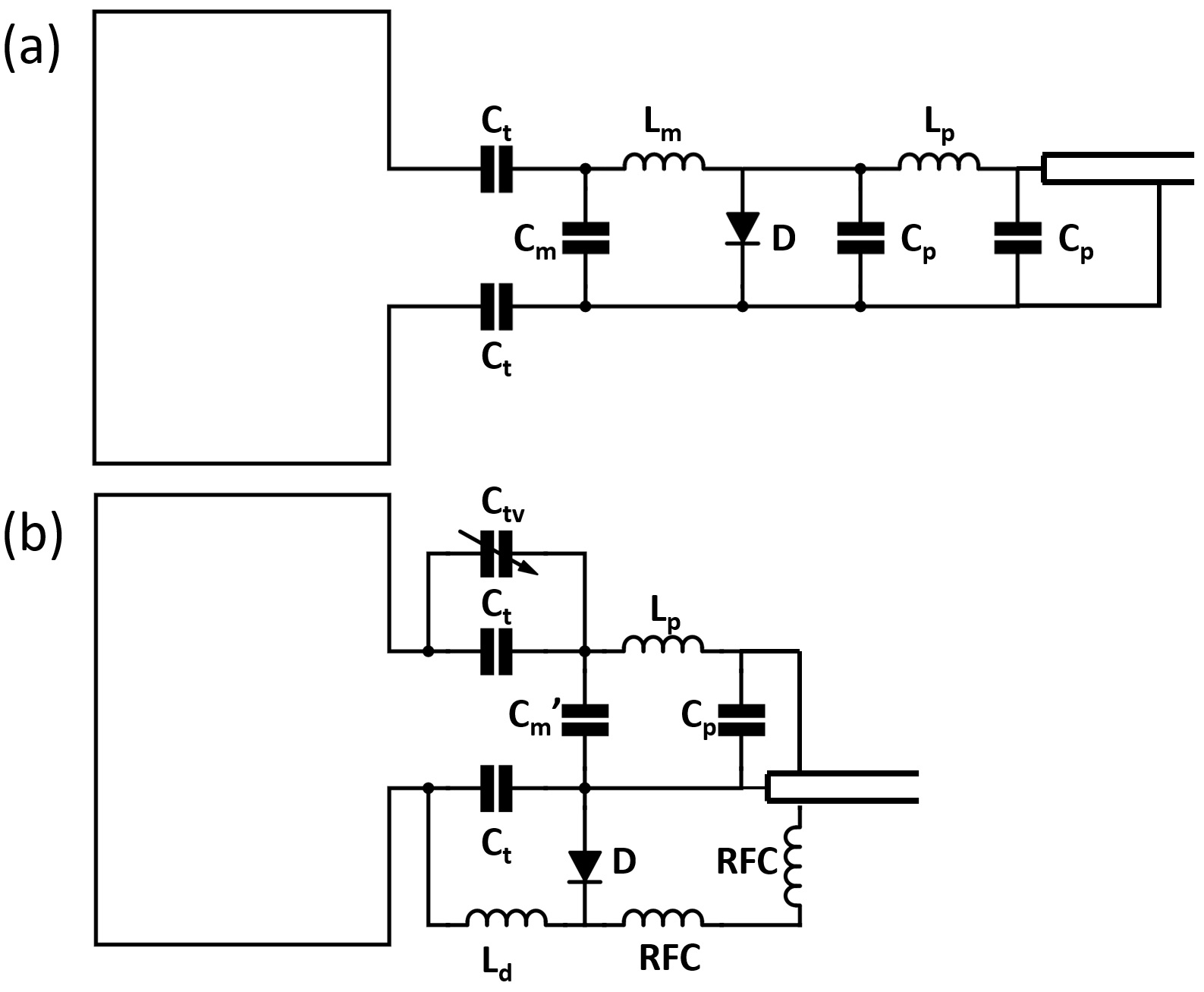
Circuit diagram of the receive-only coil elements is proposed in Figure 1. The proposed design allowed independent development of tuning, matching, active detune traps and phase shifters. This independency eliminated the tedious iterative work that is typical throughout the fabrication of the array elements. The physical length of the new circuit design is also shorter, and the reduced length helped with fitting extra coil elements in the limited space.
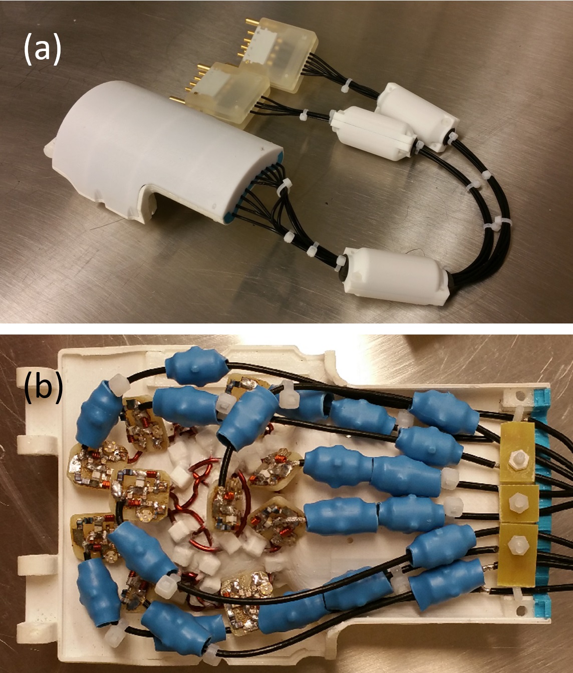
The array was built on a coil former that was designed to attach to our previously reported head-restraining helmets.14-16 Soccer ball pattern 17 of the receiving coil array was projected onto the coil former as fiducial marks in SolidWorks, and the coil former was 3D printed using polylactic acid (PLA) material. 3D-printed PLA coil clips were used to mount the coils by fusing the clips onto the coil former with tetrahydrofuran solvent. The ~0.2 mm tolerance of the coil clips allowed fine adjustment for the optimization of geometric decoupling. PLA cement was made by dissolving recycled PLA material into tetrahydrofuran, and the cement was applied on the coil clips to permanently secure the coils after the geometric decoupling is optimized (Figure 2).
An individualized helmet with molded-in foam padding was made for each marmoset. Based on the MRI of a marmoset, a mold was designed in SolidWorks and 3D printed using water-soluble polyvinyl alcohol (PVA) material. The PVA mold was placed under the helmet, and two-part urethane foam was injected into the space in between using a mixing syringe. Once the foam padding was cured, the entire assembly was soaked in water to remove the PVA mold. After the foam was dried and trimmed, the conforming 2-mm thick foam padding was embedded under the custom-made helmet.
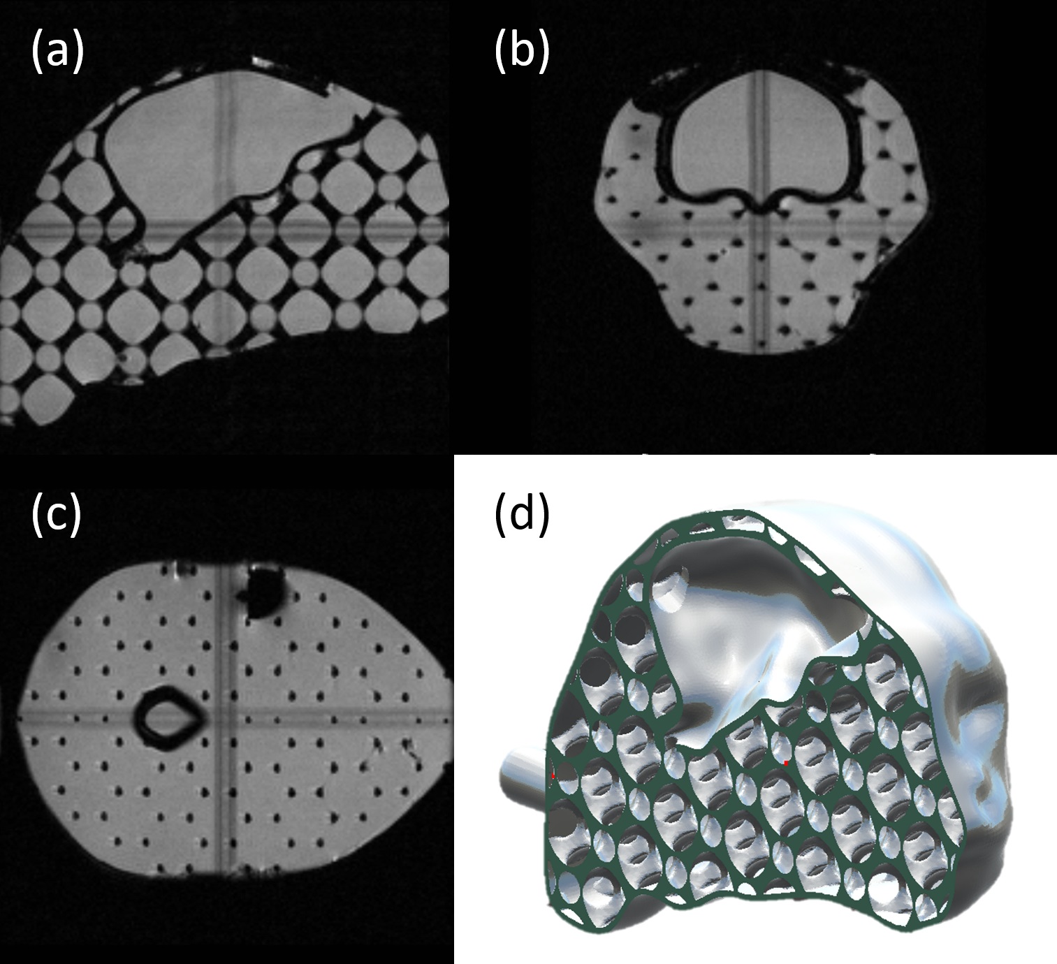
A head-and-brain phantom (Figure 3) was designed and filled with 4.9 g/L saline and 0.5 mM Gd to help with the development and testing of the head coil array. MR images of both the phantom and of the awake marmoset were used to evaluate the performance of the coil array.
Results
All 10 coil elements were tuned to 300.128 MHz and noise matched to 50 Ohm (S11 < - 21 dB) when the array was loaded with the phantom. The active detune trap achieved an uncompromised performance of 45 dB isolation when a 22 nH inductor was used to resonate with the 12 pF tuning capacitor. Phase shifters were installed to achieve 24±5.7 dB of preamp decoupling. Unloaded to loaded Q ratios were measured (Channel 1 to 10): 1.19, 1.15, 1.13, 1.10, 1.07, 1.09, 1.10, 1.14, 1.13 and 1.2.
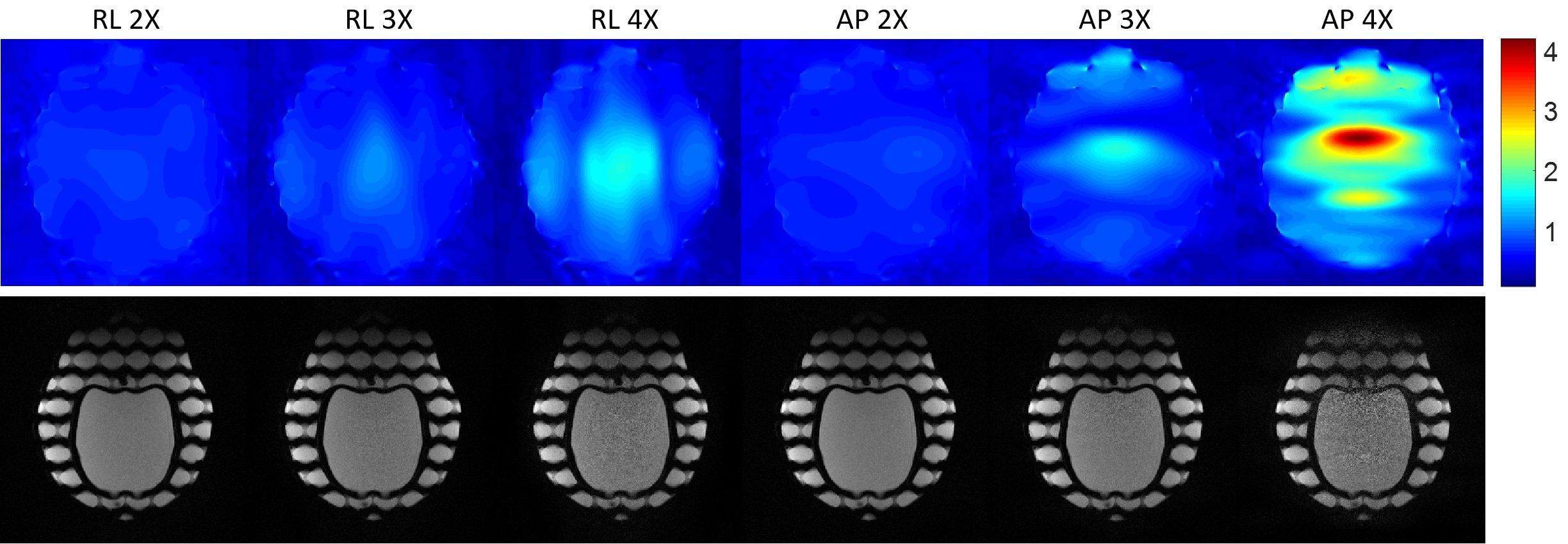
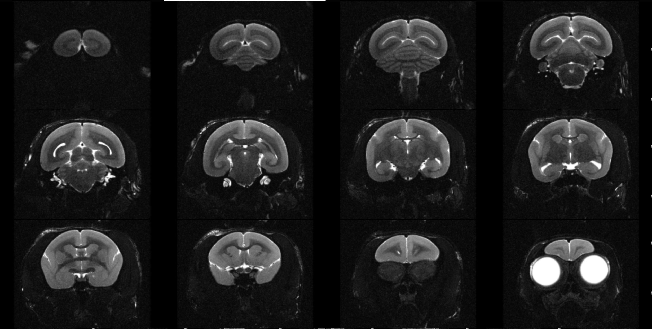
Phantom images showed that the 10-channel coil array present 1.83, 1.90, 2.02, 2.54 and 2.62 times SNR gain over the transmitting volume coil at the center of the brain, frontal, temporal, occipital and parietal lobes, respectively. G-factor maps and GRAPPA images showed minimal SNR reduction when 3X acceleration was used along the right-left or the anterior-posterior direction (Figure 4). In vivo images (Figure 5) showed good sensitivity and contrast over the entire marmoset brain.
Discussion
Because phased array coils for small-animal imaging are usually built in tight spaces, iterating capacitor/inductor values throughout the fabrication of the array is difficult. With the streamlined design developed here, replacing components throughout the process of coil development is no longer necessary, and the performance of each individual element is not compromised. The new molded-in foam padding does not shrink and provides perfect fit for the marmoset every time, and increases the marmosets’ comfort.
As a result, the proposed design showed better decoupling among coil elements and thus enabled better accelerated parallel imaging compared to that of our previous coil array.14 This work will greatly improve the quality of awake marmoset brain imaging for ongoing neurovascular studies.
Acknowledgements
Stephen Dodd, National Institute of Neurological Disorders and Stroke, National Institutes of Health, Bethesda, MD, United States.References
1. Kishi, N., et al., Common marmoset as a new model animal for neuroscience research and genome editing technology. Dev Growth Differ, 2014. 56(1): p. 53-62.
2. Okano, H., et al., The common marmoset as a novel animal model system for biomedical and neuroscience research applications. Semin Fetal Neonatal Med, 2012. 17(6): p. 336-40.
3. Solomon, S.G. and M.G. Rosa, A simpler primate brain: the visual system of the marmoset monkey. Front Neural Circuits, 2014. 8: p. 96.
4. Abbott, D.H., et al., Aspects of common marmoset basic biology and life history important for biomedical research. Comp Med, 2003. 53(4): p. 339-50.
5. Leibovitch, E., et al., Novel marmoset (Callithrix jacchus) model of human Herpesvirus 6A and 6B infections: immunologic, virologic and radiologic characterization. PLoS Pathog, 2013. 9(1): p. e1003138.
6. Ohta, S., et al., Isolation and characterization of dendritic cells from common marmosets for preclinical cell therapy studies. Immunology, 2008. 123(4): p. 566-74.
7. Attwell, D., et al., Glial and neuronal control of brain blood flow. Nature, 2010. 468(7321): p. 232-43.
8. Iadecola, C., Neurovascular regulation in the normal brain and in Alzheimer's disease. Nat Rev Neurosci, 2004. 5(5): p. 347-60.
9. Kleinfeld, D., et al., A guide to delineate the logic of neurovascular signaling in the brain. Front Neuroenergetics, 2011. 3: p. 1.
10. Lauritzen, M., Relationship of spikes, synaptic activity, and local changes of cerebral blood flow. J Cereb Blood Flow Metab, 2001. 21(12): p. 1367-83. 11. Masamoto, K. and I. Kanno, Anesthesia and the quantitative evaluation of neurovascular coupling. J Cereb Blood Flow Metab, 2012. 32(7): p. 1233-47.
12. Liu, J.V., et al., fMRI in the awake marmoset: somatosensory-evoked responses, functional connectivity, and comparison with propofol anesthesia. Neuroimage, 2013. 78: p. 186-95.
13. Pisauro, M.A., et al., Fast hemodynamic responses in the visual cortex of the awake mouse. J Neurosci, 2013. 33(46): p. 18343-51.
14. Papoti, D., et al., Design and implementation of embedded 8-channel receive-only arrays for whole-brain MRI and fMRI of conscious awake marmosets. Magn Reson Med, 2016.
15. Papoti, D., et al., An embedded four-channel receive-only RF coil array for fMRI experiments of the somatosensory pathway in conscious awake marmosets. NMR Biomed, 2013. 26(11): p. 1395-402.
16. Silva, A.C., et al., Longitudinal functional magnetic resonance imaging in animal models. Methods Mol Biol, 2011. 711: p. 281-302.
17. Wiggins, G.C., et al., 32-channel 3 Tesla receive-only phased-array head coil with soccer-ball element geometry. Magn Reson Med, 2006. 56(1): p. 216-23.
Figures