2661
Fifteen-channel receive coil for high acceleration rates in UHF marmoset imaging1Centre for Functional and Metabolic Mapping, The University of Western Ontario, London, ON, Canada
Synopsis
A 15-channel receive coil, in conjunction with a 2-channel transmit coil, was developed for imaging the common marmoset at 9.4T. The high channel count produced low geometry factors while accelerating in EPI acquisitions, thereby reducing geometric distortions with minimal impact on the SNR. This demonstrates the utility and feasibility of employing higher channel counts for functional imaging of the marmoset.
Purpose
Recently, the common marmoset (Callithrix jacchus) has emerged as an important animal model for studying brain function1,2. This has created a need for specialized radiofrequency coils that can produce the SNR required for high-resolution structural and functional imaging. For functional studies, the RF coil must be comprised of multiple channels (typically greater than or equal to four3,4) to allow for parallel imaging—this allows for shorter echo trains to reduce geometric distortions. A 15-channel receive coil has been developed to allow for high acceleration rates to be attained with low geometry factors.Methods
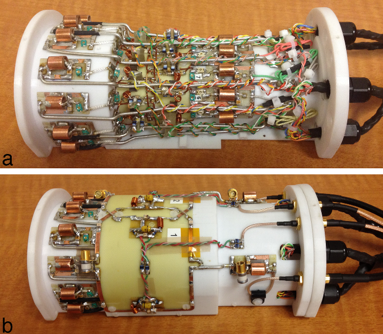
All imaging was performed on a 9.4T horizontal-bore animal MRI scanner with a 12-cm-diameter gradient coil. The 15-channel receive coil was comprised of two overlapped and offset rows (one row of eight elements and one row of seven elements), with each element measuring 17 mm by 28 mm. Elements were mounted on an inverted U-shaped former measuring 51 mm (left-right), 37 mm (superior-inferior), and 48 mm (anterior-posterior). The receive coil was designed to accommodate a head clamp to be used for immobilization during awake imaging; however, all imaging in this study was performed on lightly anesthetized animals.
A parallel-resonant active detuning circuit and fast-blow fuse were integrated into each coil loop. A series capacitor for preamplifier decoupling and a parallel capacitor for matching were located at the drive port of each element. A choke balun was placed at the input of each coil to create a balanced input to the preamplifier. Due to space constraints imposed by the diameter of the bore (12 cm), low-input-impedance preamplifiers were located on the front of the magnet and connected to the coils via a 113-cm (a multiple of lambda/2) high-density cable. A 2-channel coil with geometric overlap was used for transmission. Photographs of the transmit and receive coils are shown in Fig. 1.
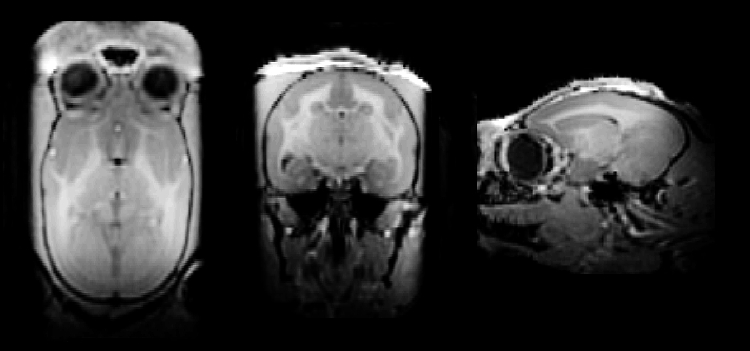
Geometry-factor maps were calculated from gradient-echo images (FOV: 64 x 48 mm; BW: 50 kHz) of a 4% agar / 50-mM NaCl phantom. Temporal SNR was calculated from an EPI time series (resolution: 500-μm isotropic, TE/TR: 15/1500 ms, BW: 500 kHz, slices: 40, number of volumes: 400). Images were acquired with a 2-fold reduction factor in the left-right direction and 9/10 partial k-space, resulting in an effective acceleration rate of 2.22 and an echo-train length of 36. An MP2RAGE image with 500-μm isotropic resolution was acquired to demonstrate the resultant image quality (TE/TR: 1.4/5.1 ms, TI1/TI2: 1000/3000 ms, BW: 45 kHz, flip angles: 5°/7°, number of averages: 4, acquisition time: 28 min 28 s).
Results
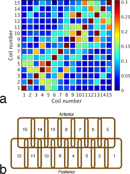
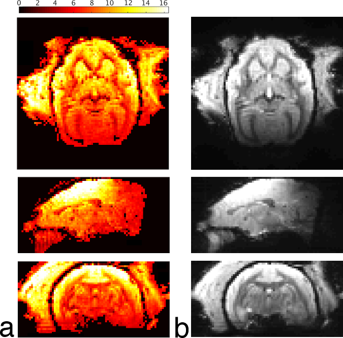
The mean S12 between adjacent receive elements was -17 dB. When combined with a mean preamplifier decoupling of -10 dB, the mean and maximum noise correlation was 8.7% and 31%, respectively (Fig. 2). Preamplifier decoupling could be improved to -15 dB by reducing the length of the cable between the coil and the preamplifier. Active detuning provided greater than 35 dB of isolation during transmission. In vivo measurements of temporal SNR are shown in Fig. 3 with the corresponding images from the mean volume of the EPI time series. Inverse geometry-factor maps are shown in Fig. 4.Discussion
The highest temporal SNR was achieved at the superior aspect of the brain, with the enlarged coil width (to accommodate a head-fixation helmet, the temporal muscles, and ears) causing the temporal SNR to decrease in the temporal lobes. The visual cortex proves to be a consistently difficult region to attain high SNR for animals placed in the sphinx position, due to the increased distance of the coil to the brain. In this region, temporal SNR is approximately 2.5-fold lower than the superior aspect of the head; however, an MP2RAGE image (Fig. 5), demonstrates good image quality and uniform contrast throughout the brain.
The echo-planar image had minimal geometric distortions over the brain region due to the reduced echo-train length. The 15-channel coil was capable of achieving acceleration rates of 2-fold in the anterior-posterior direction and 3-fold in the left-right direction with less than a 20% increase in noise amplification during reconstruction.
Conclusions
The 15-channel receive coil was capable of producing low geometry factors with high acceleration rates, thereby minimizing geometric distortions in echo-planar images with minimal degradation in SNR. This demonstrates the utility of employing higher channel counts, compared to conventional coils, for functional imaging of the marmoset.Acknowledgements
The authors would like to thank Nicole Hague and Ashley Kirley for animal care and preparation and Dr. Alex Li for scanning assistance.References
1. Okano H, Hikishima K, Iriki A, Sasaki E. The common marmoset as a novel animal model system for biomedical and neuroscience research applications. Seminars in Fetal & Neonatal Medicine 2012; 17: 336-340.
2. Ghahremani M, Hutchison RM, Menon RS, Everling S. Frontoparietal functional connectivity in the common marmoset. Cereb. Cortex 2016. DOI: 10.1093/cercor/bhw198
3. Papoti D, Yen CCC, Mackel JB, Merkle H, Silva AC. An embedded four-channel receive-only RF coil array for fMRI experiments of the somatosensory pathway in conscious awake marmosets. NMR Biomed. 2013; 26: 1395-1402.
4. Papoti D, Yen CC, Hung CC, Ciuchta J, Leopold DA, Silva AC. Design and implementation of embedded 8-channel receive-only arrays for whole-brain MRI and fMRI of conscious awake marmosets. Magn. Reson. Med. 2016.
Figures