2659
Structure Adjustment of Surface Dipole Antenna Elements for Body Imaging at 7 Tesla MRI1Department of Biomicrosystem Technology, Korea University, Seoul, Korea, Republic of, 2Department of Electronics and Information Technology, Korea University, Seoul, Korea, Republic of, 3Korea Basic Science Institute, Cheongju, Chungcheongbuk-do, Korea, Republic of, 4Research Institute for Advanced Industrial Technology, Korea University, Sejong City, Korea, Republic of, 5ICT Convergence Technology for Health & Safety, Korea University, Sejong City, Korea, Republic of
Synopsis
In ultra-high-field magnetic resonance imaging (UHF-MRI), body imaging suffers from B1 inhomogeneity due to relatively short wavelength. A range of new radio frequency (RF) coil designs has been proposed to overcome this problem. As previously reported, dipole antenna had been proposed to address this B1+ inhomogeneity problem for body imaging. In this paper, structural adjustment of dipole antenna has been tried for parallel transmission to improve overall B1+ homogeneity. Surface dipole antennas with several structures are tried and compared with our top-hat dipole antenna array reported previously. Also, static RF shimming was employed to evaluate the B1 uniformity.
Introduction
Although ultra-high field magnetic resonance imaging has been of interest for many years due to its high SNR and other imaging capabilities, achieving good B1+ homogeneity from the transmit coil is still a big challenge due to the relatively short wavelength of the RF wave. Radiative antenna arrays have been previously proposed to overcome this problem while increasing the total transmission efficiency [1]. In this paper, structural adjustments of dipole antenna with various tilting structures have been tried to improve B1+ homogeneity. Electromagnetic (EM) simulation has been performed, and B1+ field uniformity and SAR are compared for various design parameters. RF shimming was evaluated to achieve better optimization for a given SAR.Materials and Methods
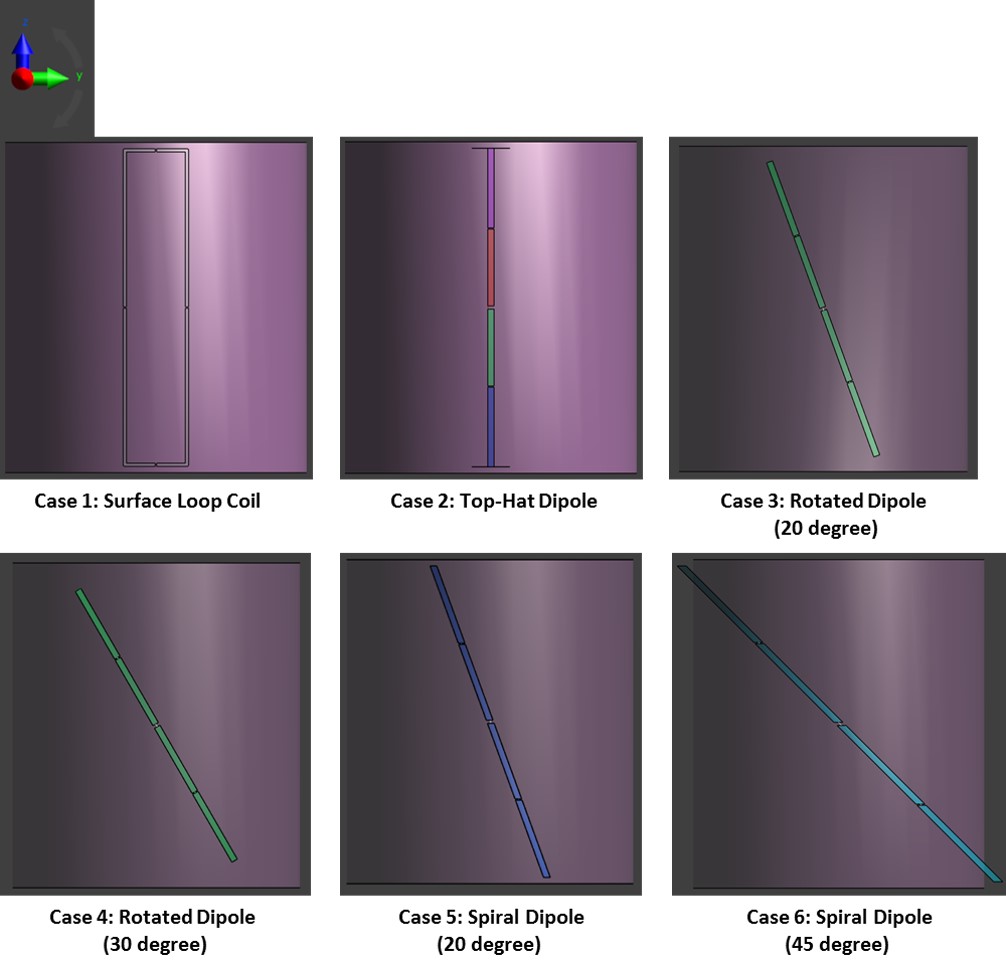
Conventional dipole antenna consists of two conductive lines such as microstrips or rods, which are symmetric in both sides (arms), with the source feed at its center. A top-hat dipole antenna is a combination of conventional dipole antenna and pieces of copper [2]. The first structural adjustment refers to the rotation of dipole antenna and the second adjustment is the dipole antenna with curved and rotated shape, like a spiral shape. We will call it a spiral dipole antenna. A surface loop coil of rectangular shape (10 cm W x 50 cm L) is also considered for comparison. Figure 1 shows the top view of these antennas described.
EM simulation analysis based on FDTD method was performed using Sim4Life [3]. For 8-channel configuration, the 8 elements are equally distributed in radial direction (52 cm D) identical to inner diameter of the Achieva 7 T (Philips, The Netherlands) magnet bore. A uniform digital phantom (46 cm D × 52 cm H) with the dielectric properties of oil was used (relative permittivity of 11.74 and the conductivity of 0.764 S/m).
The RF shimming optimization method was previously proposed to improve the B1 uniformity in a selected region of interest (ROI) by optimizing the relative magnitude and phase of RF power delivered to each transmit element [4,5]. To obtain the complex weight of each element, the superposition of linear system was used to solve the optimization equation using the conjugate gradient method [6]. The least square method is implemented in MATLAB as follows:
Solve Ax = b
Or minimize ǁ Ax – b ǁ
Or solve (ATA +sI)x = ATb
where A = B1 from individual coil, s = regularization parameter for maximizing uniformity (must be positive), x = magnitude of power delivered to individual coil, AT = transpose of matrix A, I = identity matrix, and b = desired B1 field from combined coil.
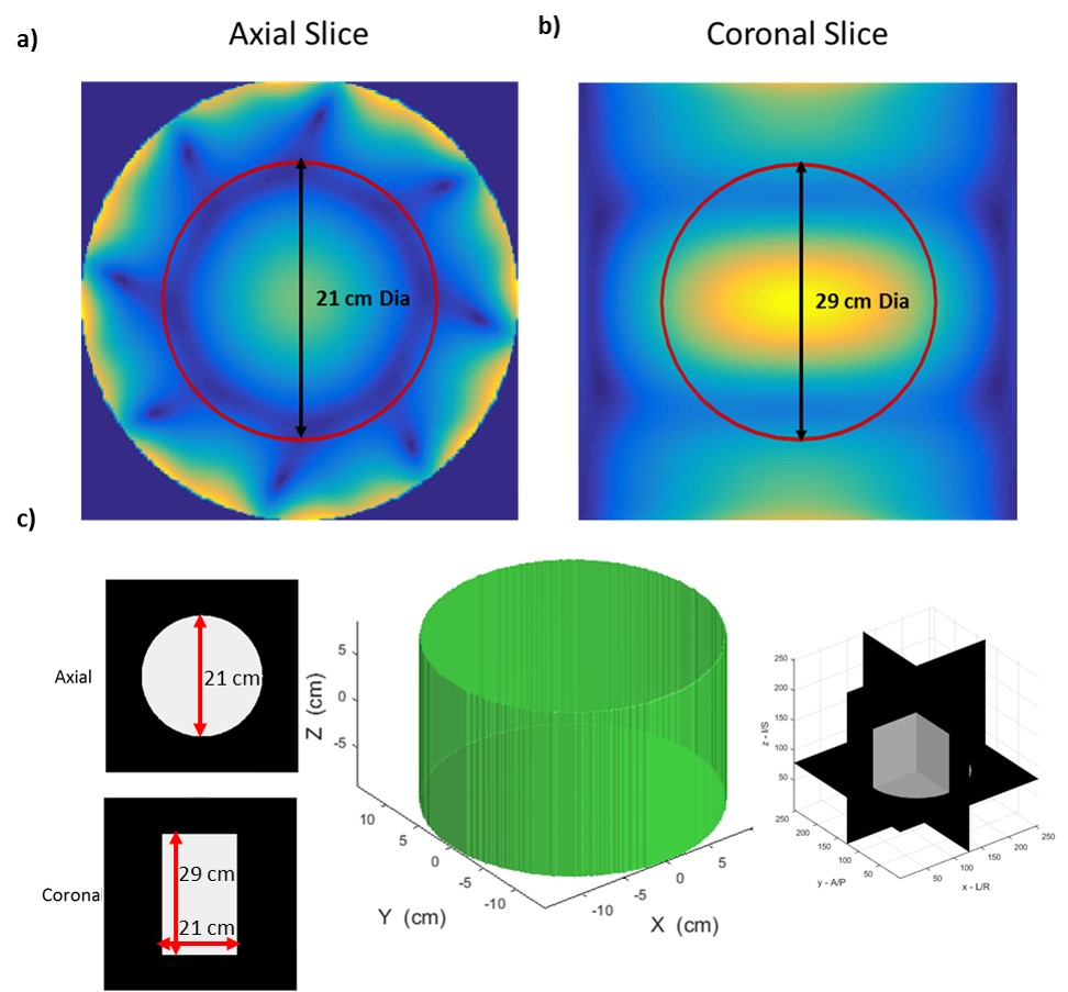
After the optimization for shimming, the power values applied to each element were normalized to produce a rectangular excitation pulse with a duration of 1 msec at the center of the coil and resultant 90° flip angle (B1+ field value of 5.87 μT). The RF shimming optimization was evaluated in both 2D and 3D ROI’s. The 2D ROI in axial plane is 21 cm and coronal plane is 29 cm in diameter, respectively and 3D ROI is in a cylindrical shape with 21 cm in height and 29 cm in diameter (Fig. 2).
Results and Discussions
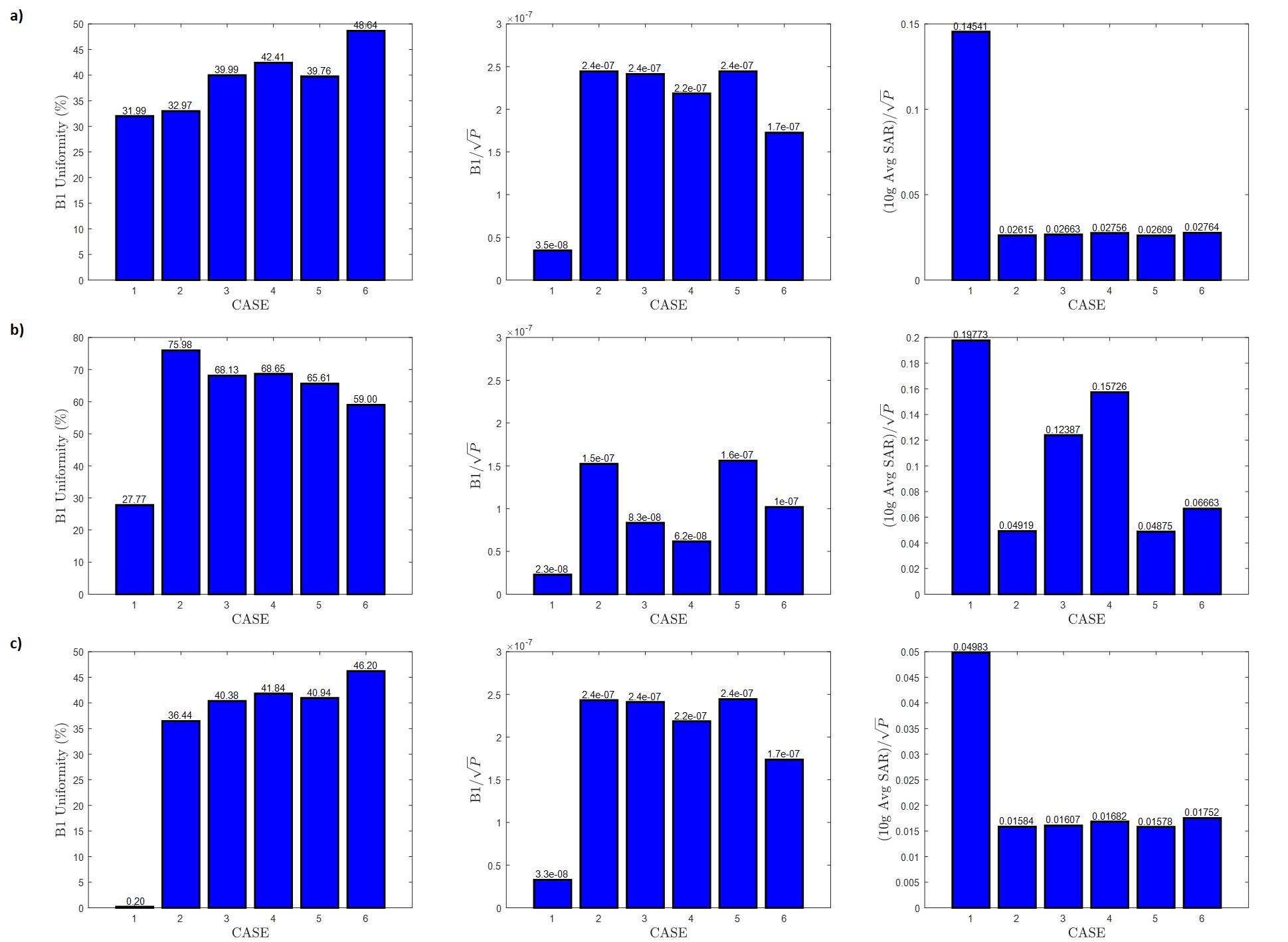
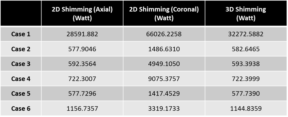
All the dipole antennas were tuned and matched to 298 MHz using Sim4Life matching toolbox. Figure 3 shows B1+ uniformity (%), B1 efficiency, and 10g Average SAR for RF shimming optimization in 2D ROI axial planes, 2D ROI coronal planes, and 3D ROI. And it shows the top-hat dipole antenna has the highest B1 efficiency. However, the spiral dipole antenna (45 degree) shows the best B1 uniformity in the axial plane. From RF shimming optimization in coronal plane, top-hat dipole antenna offers the highest B1 uniformity and lowest SAR. In 3D ROI based RF shimming optimization, top-hat dipole antenna offers the highest B1 efficiency, however, spiral dipole antenna (45 degree) shows the highest B1 uniformity with 10% increase in uniformity. Table 1 shows the total power delivered to 8-channel array to achieve 90° (5.87 μT) at the center for 2D ROI shimming (axial), 2D ROI shimming (coronal), and 3D ROI shimming in the uniform digital phantom for the 6 cases.Conclusion
The B1 uniformity can be improved by structural adjustment of dipole antenna. The top-hat dipole antenna array offers the highest B1 efficiency while spiral dipole antenna shows the maximum uniformity. Application of RF shimming showed B1 uniformity enhancement and they have proved to be very effective in SAR reduction. In future work, these antennas array will be verified experimentally in both phantom and in-vivo studies.Acknowledgements
This research was supported by the Korea Basic Science Institute under the R&D program (Project No. D36700) supervised by the Ministry of Science, ICT, and Future Planning and the MEST-BMBF University Cooperation Programme: NRF-2012K1A3A1A24025536. Authors thank ZMT for providing free license of Sim4Life used in this study.References
1. Raaijmakers, A. J. E. et al. Design of a radiative surface coil array element at 7 T: The single-side adapted dipole antenna. Magnetic Resonance in Medicine. 2011; 66(5): 1488-1497.
2. Kumar, S. et al. Improved B1+ along Z-direction using top-hat dipole antenna pTX array for body imaging at 7 Tesla. ISMRM. 2016; 1801.
3. Sim4Life by ZMT, <http://www.zurichmedtech.com>
4. Metzger, G.J. et al. Local B1+ shimming for prostate imaging with transceiver arrays at 7T based on subject-dependent transmit phase measurements. Magnetic resonance in medicine. 2008; 59(2): 396-409.
5. Collins, C. M. and Smith, M. B. Signal-to-noise ratio and absorbed power as functions of main magnetic field strength, and definition of “90°” RF pulse for the head in the birdcage coil. Magnetic Resonance in Medicine. 2001; 45(4): 684-691.
6. Hestenes, M. R. and Stiefel, E. Methods of conjugate gradients for solving linear systems. Journal of Research of the National Bureau of Standards. 1952; 49(6): 409–43.
Figures