2658
Optimal array configuration for cerebral cortex MRI at 7T: six center-fed dipoles with two loops RF coil array1CIBM - LIFMET, Ecole Polytechnique Fédérale de Lausanne, Lausanne, Switzerland, 2Department of Radiology, University of Geneva, Geneva, Switzerland, 3Department of Radiology, University of Lausanne, Lausanne, Switzerland, 4CIBM-AIT, Ecole Polytechnique Fédérale de Lausanne, Lausanne, Switzerland
Synopsis
Searching for optimal RF coil array for whole-brain MR applications, central-fed dipole was compared with fractionated dipole in a single and RF coil array configurations with combination of loop coils in measurements and electromagnetic field simulations in terms of B1+ transmit efficiency, field uniformity, SAR and mutual coupling in an array. High transmit field performances were shown over the cerebral cortex by using phase-only shimming with six center-fed dipoles with two loops RF coil array on experimentally measured B1+-maps and anatomical MR images.
Introduction
Dipole antennas were proposed as an alternative to loop coils or microstrips as they were shown to have better penetration depth and field uniformity, at 7T1. Several earlier designs such as radiative, bow-tie, fractionated, snake or dipole-loop configurations have been investigated for body and brain magnetic resonance (MR) imaging1-6. In this study, we made a comparison between a central-fed dipole and a fractionated dipole configuration with respect to B1+ transmit efficiency, excitation uniformity, SAR and mutual coupling in a single coil and 8-channel coil array.
Methods
Center-fed and fractionated dipole array designs:
An 8-channel center-fed dipole
and an 8-channel fractionated dipole array were built with copper printed on
flexible PCB and tuned/matched to 297.2MHz/50Ohms. B1+-maps7
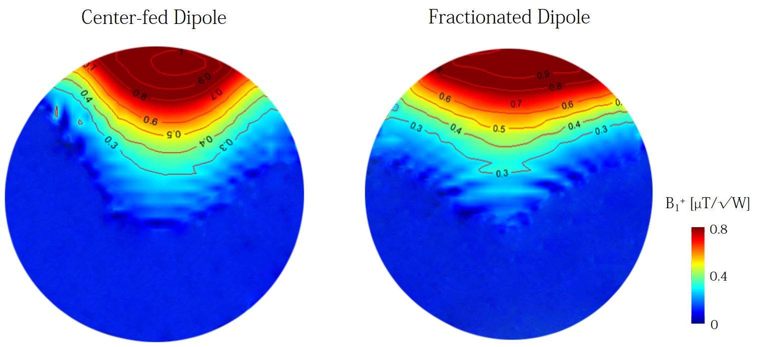
were experimentally measured on a spherical phantom for single center-fed and
fractionated dipole (170mm-length,25mm-width, an inductor placed in the
fractionated part) (Fig.1). S-parameter matrices of each array were measured on
a network analyzer (Agilent Technologies 5071C-ENA Series,USA).
Electromagnetic Field Simulations:
Finite difference time
domain (FDTD) simulations were performed on Sim4Life 3.1 (ZMT,Switzerland) on a
Virtual Family human model8 for three RF coil array configurations: an
8 fractionated dipole array; a six fractionated/six center-fed dipole array with
two loop coils covering the frontal lobe region. All coils were tuned/matched
to 297.2MHz/50Ohms (>-15dB).
Six center-fed dipole with two loop coil array design:
Compared to placing two
dipoles on the frontal lobe, two loop coils (95x85mm2 each)
demonstrated higher transmit field efficiency and lower mutual coupling by coil
overlapping. While five of the dipoles were placed around the occipital and
temporal lobes of the brain, the sixth dipole was placed around the parietal
lobe to provide additional B1+ in the upper region of the
brain. Dipoles were copper-printed (35μm-thickness,25mm-width) on flexible PCB (FR4,0.1mm-thickness)
and dipole length was varied from 157mm to 186mm according to the shape of the
brain. The coils were tuned/matched (S11>-15dB,S12>-8.5dB) using
fixed/variable capacitors and inductors. Common-modes on the coaxial cables
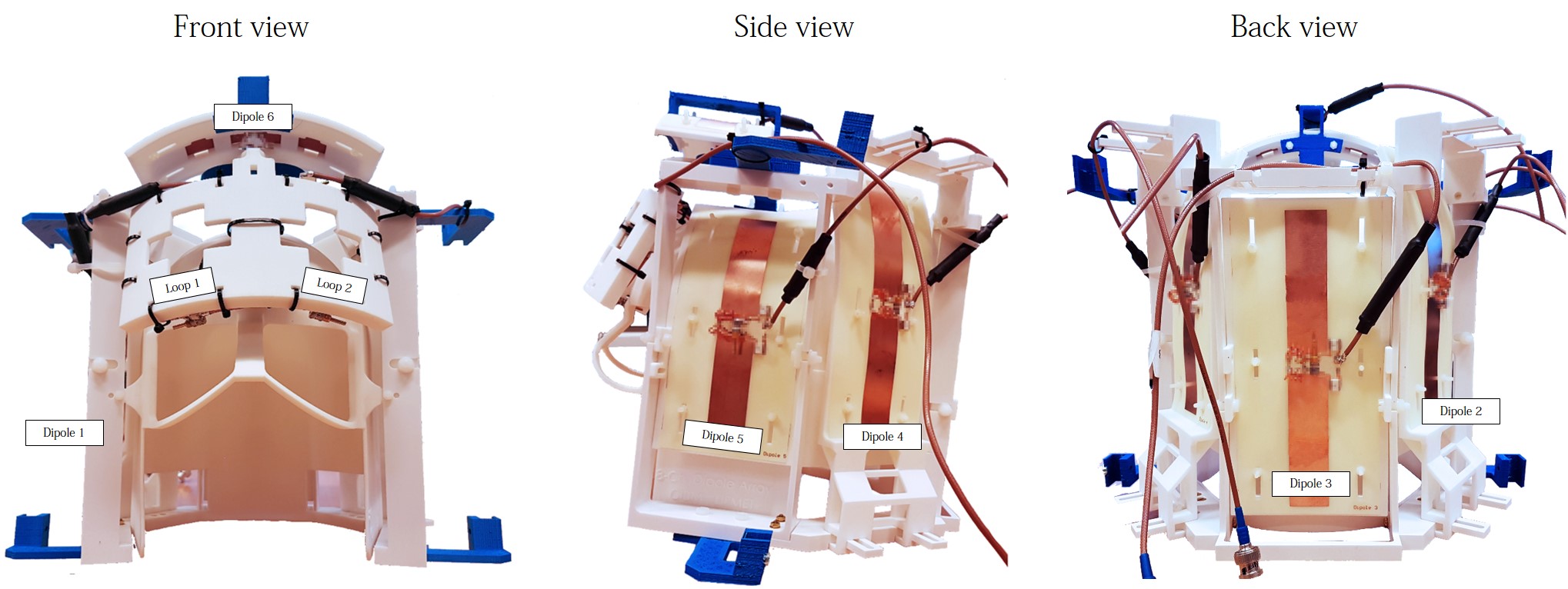
were diminished with balun-transformers. Conformal housing (Fig.2) was designed
(Solidworks,DassaultSystems,France) and 3D-printed (EOSINT P395,EOS,Germany) in
nylon (EOS,PA2200).
MR Experiments:
B1+-maps
and anatomical images from a healthy male volunteer were acquired using a
Magnetom 7T MR scanner with an 8x1kW RF-amplifier (Step1,Siemens,Erlangen,Germany).
Optimal RF phases9 were calculated with a PSO method10 and the
following sequences were used: 3D-Turbo-Spin-Echo (0.8x0.8x1mm3,TR/TE=2000/120ms,TA=10min,GRAPPA=2,Averages=1),
multi-slice GRE (0.3x0.3x3mm3,TR/TE=1000/16ms,TA=5min30s,GRAPPA=2),3D-MP2RAGE
(2x2x2mm3,TR/TE =5500/1.67ms, TA=5min,GRAPPA=2).
Results
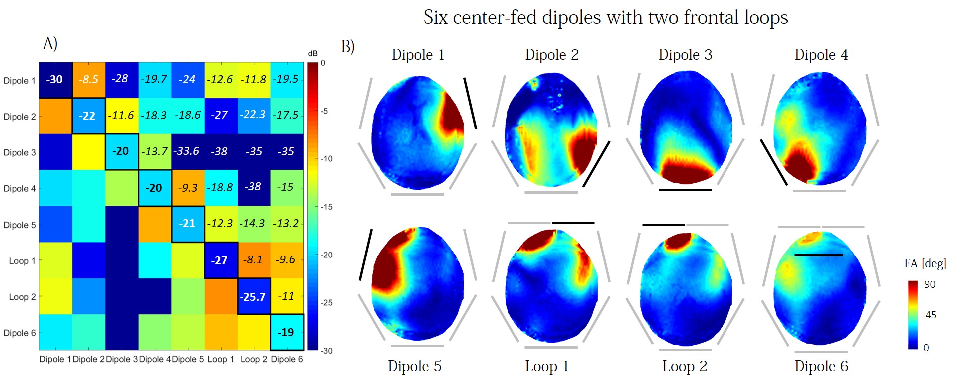
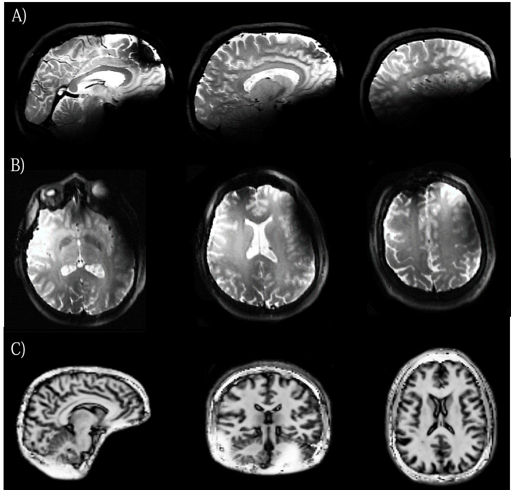
While the center-fed dipole yields higher transmit efficiency in deeper regions, the fractionated dipole provides larger longitudinal field coverage (Fig.1). Measured mutual coupling for 8-channel center-fed and fractionated dipole arrays demonstrate similar results (S12>-8.1dB and S12>-7.4dB, respectively). Moreover, the $$$B_{1,mean.ROI}^+/\sqrt{SAR_{10g,max}}$$$ value does not exhibit significant differences for center-fed and fractionated arrays (0.50 vs 0.53$$$\mu T\sqrt{kg}/W$$$). As no substantial gain is observed using the fractionated dipole, the central-fed array was further investigated. Six center-fed dipoles with two frontal loop coil array exhibits a high transmit field in close vicinity to the array element (Fig.3B). However, coupling is visible between dipoles 3 and 2 and dipole 5 with loop 2 (Fig.3A). A mean flip angle of $$$90°\pm16° (SAR_{10g,max}=0.89W/kg)$$$ and $$$90°\pm6° (SAR_{10g,max}=0.55W/kg)$$$ is achieved at 84V/channel and 96V/channel, over the ROIs, by using phase-only RF shimming on central transverse and sagittal slices (Fig.4A). High-resolution (0.3x0.3x3mm3) multi-slice GRE images (Fig.4B) demonstrate high signal uniformity. High-resolution (0.8x0.8x1mm3) 3D-TSE images (Fig.5A-B) exhibit good coverage of cerebral cortex and homogeneous signal over multiple slices in the brain. The dark line visible in the frontal lobe is an inversion band resulting from the high transmit efficiency of the two loops in their close vicinity. 3D-MP2RAGE images (Fig.5C) demonstrate that whole-brain is covered by phase-only RF shimming applied on a sagittal slice.Discussion and conclusion
Optimal array configuration for cerebral cortex imaging was shown for a six center-fed dipole, two frontal loop coil array by B1+-maps and anatomical images with phase-only RF shimming. This conformal coil array design exploited the placement of 6 dipoles on the temporal, occipital and parietal lobes of the brain, and two loop coils on the frontal lobe. No decoupling treatment was applied for the neighboring dipoles. The 8-channel array presented here demonstrates high transmit performance allowing any desired flip angle over the cerebral cortex by using phase-only RF shimming. High coverage and good field uniformity were obtained on high-resolution (0.8x0.8x1mm3) TSE, high-resolution (0.3x0.3x3mm3) GRE and MP2RAGE images. Future work will include the construction of independent receivers to increase the signal and allow for higher acceleration factors. We concluded that this 8-channel coil array configuration is remarkably efficient, in terms of coverage and B1+ performances, and can be used for multiple studies in the human brain at 7T.Acknowledgements
This study was supported by Centre d’Imagerie BioMédicale (CIBM) of the UNIL, UNIGE, HUG, CHUV, EPFL and the Leenaards and Jeantet Foundations.
References
[1] Raaijmakers AJE et al. Magn. Reson. Med. 2011; 66: 1488-1497
[2] Oezerdem C et al. Magn. Reson. Med. 2016; 75(6): 2553-2565
[3] Duan Q et al. Magn. Reson. Med. 2015; 74(4): 1189-1197
[4] Raaijmakers AJE et al. Magn. Res. Med. 2016; 75(3): 1366-1374
[5] Steensma B et al. Proc. Intl. Soc. Magn. Reson. Med. 24 (2016): 395
[6] Chen G et al. Proc. Intl. Soc. Magn. Reson. Med. 23 (2015): 3133
[7] Eggenschwiler F et al. Magn. Reson. in Med. 2012; 67: 1609-1619
[8] Gosselin MC et al. Phys. in Med. and Biol. 2014; 59(18)
[9] Metzger GJ et al. Magn. Reson. Med. 2008; 59(2): 396-409
[10] Clement J et al. Proc. ESMRMB, 503, 2016
Figures