2655
Towards a Flexible Transceiver Array for 7 T Cardiac MRI: Evaluation of Decoupling Ring Effects1Division MR Physics, Center for Medical Physics and Biomedical Engineering, Medical University of Vienna, Vienna, Austria, 2IR4M (Imagerie par Résonance Magnétique Médicale et Multi-Modalités), Univ. Paris-Sud, CNRS, Université Paris-Saclay, Orsay, France
Synopsis
In view of building a flexible 7T 2D coil array for cardiac MRI at 7 T, transmission line resonators (TLRs) with and without decoupling ring are investigated. Using 3D EM simulation and MR measurements for single elements, it could be shown that the presence of the decoupling ring does not perturb significantly the $$$B_1^+/\sqrt{P_{input}}$$$ distribution of the TLR. 3D gradient echo images for both TLRs with and without decoupling rings have been acquired. No significant degradation in the image quality due to the presence of the decoupling ring was observed.
Purpose
Transmission line resonators (TLRs) have been applied to develop mechanically flexible arrays for high field MRI combining the advantages of parallel imaging with the possibility of form-fitting1. The aim of our work is to develop a flexible transceiver array based on TLRs for cardiac MRI at 7 T. One of the major technical challenges is the mutual decoupling between individual elements. Efficient decoupling has been demonstrated using coil annexes1 with the limitation of interfering with the coil’s geometry. Therefore, we pursue a decoupling ring-based technique2,3 for TLR arrays. In this work, we evaluate the performance of decoupling rings, including decoupling efficiency and effects on the transmit field of the TLR, using electromagnetic simulations (EMS) and MR measurements at 7 T.Methods
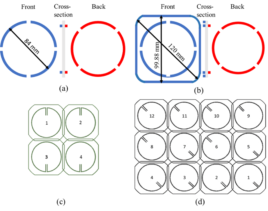
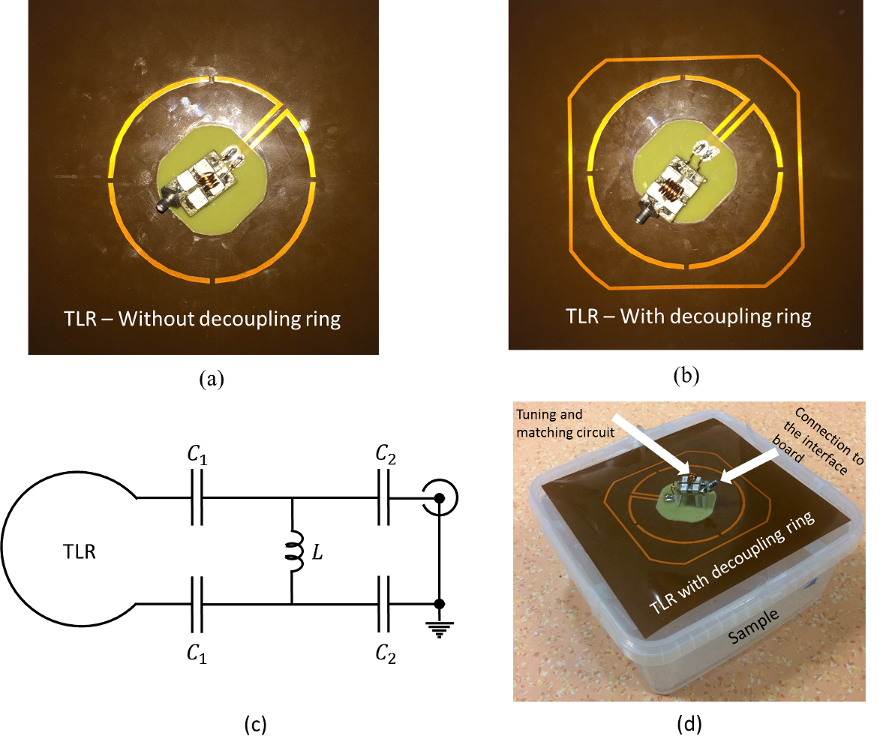
Figures 1.a,b show the schematic of TLR designs with and without decoupling ring. Each element is composed of two conductors (84 mm outer diameter, 2 mm width) deposited on both sides of a 150 µm thick polyimide substrate. In array configuration, decoupling rings of nearest neighbors are deposited on opposite sides of the substrate for overlapping (Figs. 1c,d). Decoupling optimization was done by analytically calculating the shared magnetic flux as function of the decoupling ring overlap distance3. Initially, the performance of the decoupling rings for a single element TLR, 4-element and 12-element array of TLRs was evaluated in 3D EMS (XFdtd 7.5, Remcom, USA) and circuit co-simulation4 (ADS, Keysight Technologies, USA)5. For the single element, the transmit efficiency ($$$B_1^+/\sqrt{P_{input}}$$$) with and without decoupling ring was simulated and validated by the following experiment: two TLRs with and without decoupling rings (Figs. 2a,b) were fabricated (db electronic Daniel Böck GmbH, Bregenz, Austria). Each element was tuned and matched to 297.2 MHz (1H @ 7T) using the circuit diagram shown in Fig. 2c. For MR experiments, a 160x160x70 mm3 box filled with polyacrylic acid gel with tissue-like properties was used as load (Fig. 2d). The distance between the TLRs and the phantom was 10 mm. MRI experiments were carried out on a whole body MRI scanner (Magnetom 7T MRI, Siemens Healthineers, Erlangen, Germany). Flip angle maps were acquired using the Saturated Turbo FLASH method5, applying a slice-selective saturation pulse (2 ms duration, 20 V amplitude) for both TLRs with and without decoupling ring. $$$B_1^+$$$ maps normalized to the input power were calculated using the measured flip angle maps considering an insertion loss of -1.5 dB of the coil cables and the T/R switch, which was measured on the bench. Finally, a 3D gradient echo sequence (TR/TE = 14/6.75 ms, Tacq = 2:25 min, 1x1x1 mm3 nominal resolution, 96x192x192 mm3 FOV) was used to acquire MR images of the phantom. To test decoupling efficiency, S-parameters were simulated in a 4-element array. With the results from the single TLR and the 4-element array, the final 12-element array was designed and S-parameters were simulated using 3D EMS.Results
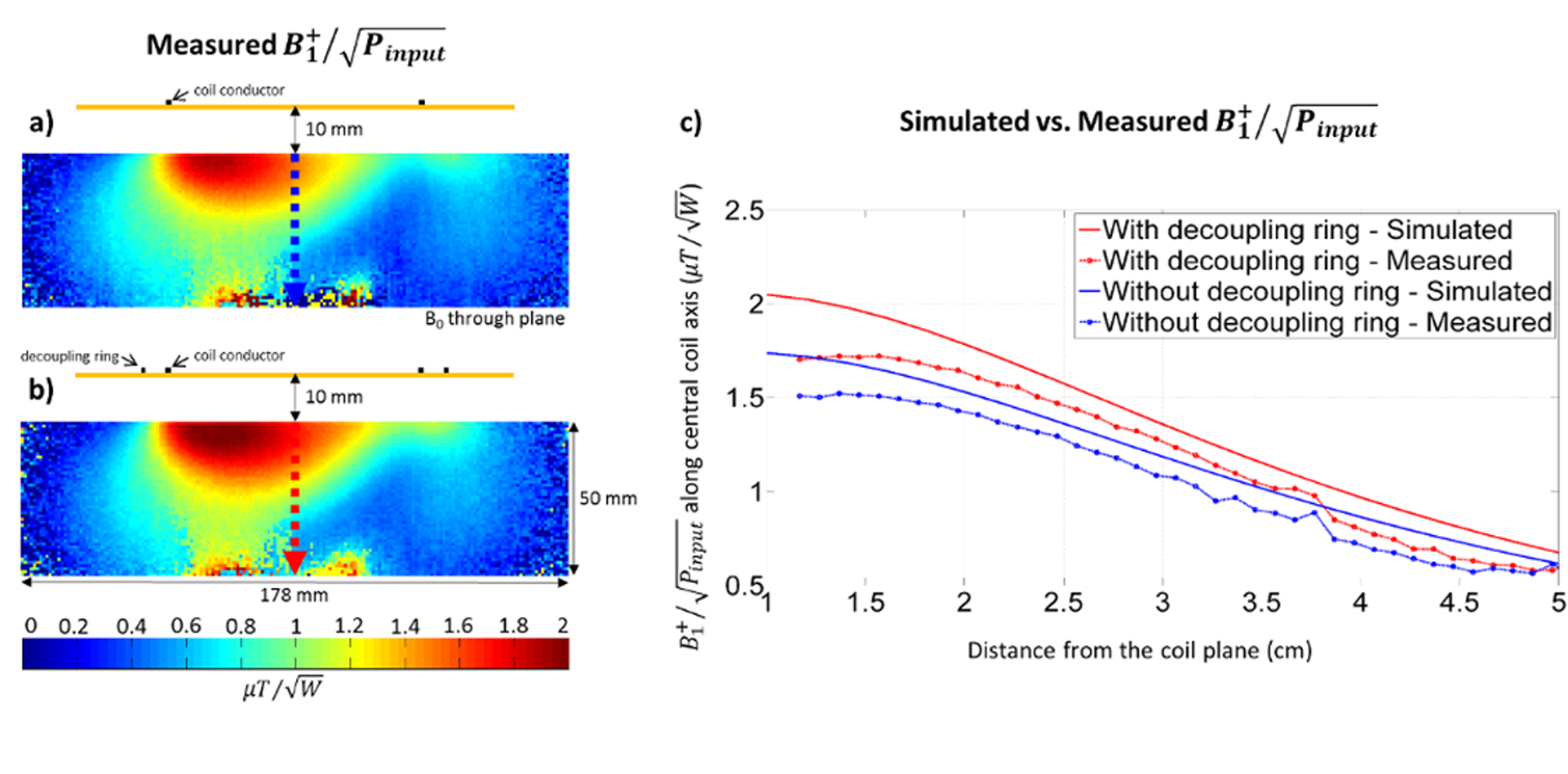
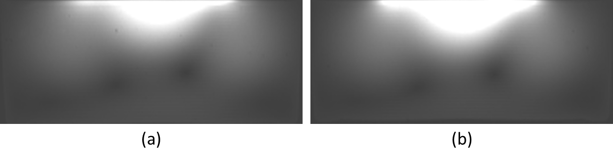
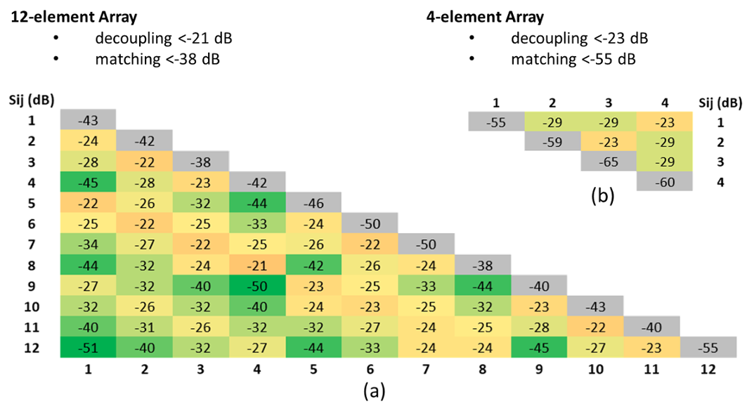
Fig. 3 shows transversal transmit efficiency maps calculated from measured flip angle maps for single TLR elements with and without decoupling ring. It was observed that transmit efficiency is slightly increased on the central TLR axis close to the TLR. Measurements are in agreement with simulation results, as shown for central axis profiles in Fig. 3c. 3D gradient echo images are shown in Fig. 4. No significant artifacts were observed for the images acquired with the TLR containing the decoupling ring. Simulated S-parameters for the 4-element and 12-element TLR arrays are shown in Fig. 5 (matching ≤ -38 dB, coupling ≤ -21 dB).Discussion
The increase in transmit efficiency close to the coil for TLRs with decoupling ring can be interpreted as a field concentration effect caused by the decoupling ring. At larger distances the profile is comparable for both TLRs with and without decoupling ring. The effect can also be observed in the acquired gradient echo images (Fig. 4): the TLR with decoupling ring has higher signal close to the coil in comparison to the TLR without decoupling ring.Conclusion
Efficient decoupling by decoupling rings was demonstrated using 3D EM simulation. MR experiments have successfully demonstrated that the presence of the decoupling ring does not degrade the transmit performance of the TLR. Also, image quality is not affected by the presence of the decoupling ring. As a next step, the 12-element flexible array of TLRs for cardiac MRI at 7 T decoupled by overlapped decoupling rings will be physically implemented in order to validate simulations and evaluate the transmit efficiency of the array.Acknowledgements
Austrian/French FWF/ANR programme Blanc grant, Nr. I1371-B24, “FLEXAR7” Austrian/French OeAD/MAEE projects WTZ/PHC Amadée FR10/2015References
[1] Kriegl R et al., Magn Reson Med 73(4):1669–1681, 2015.
[2] Lanz T et al., ISMRM 2006, p.217.
[3] Li Z et al., ESMRMB 2015, p.74.
[4] Kozlov M et al., J Magn Reson, 200(1):147-152, 2009
[5] Hosseinnezhadian S et al., ESMRMB 2016, p.85
[6] Chung S et al., Magn Reson Med 64: 439-446, 2010
Figures