2653
A Dedicated Measurement Probe for Quantitative Common Mode Measurements and Balun Efficiency.1Imaging Research Center, Cincinnati Children's Hospital Medical Center, Cincinnati, OH, United States
Synopsis
A method to measure common mode voltages and balun efficiency is described. Common mode voltages were measured with a novel common mode measurement probe and oscilloscope along a coaxial cable of a loaded loop coil which was excited with a network analyzer at 127.74MHz. The common mode measurements were performed on the loop coil without a balun and compared to the same loop coil with a balun to evaluate the common mode attenuation of the balun.
Target Audience
Researchers and engineers interested in baluns and common mode measurements and evaluation.Purpose
Common mode voltages and currents can be created when a balanced transmission line is connected to an unbalanced transmission line1. In the MR setting, common modes can create an unwanted coupling path between coils and can pose a safety hazard to the patient when one of the coils is the high-power body coil. Common mode signals can be attenuated with baluns and cable traps, and the effectiveness of these circuit elements can be measured with a variety of methods2. Mixed mode S-Parameters can be measured with a 2 port network analyzer or directly measured with a 3 port network analyzer. However, 2 and 3 port analyzers are expensive, difficult to set up and calibrate for these measurements, and do not provide a spatial distribution of the common mode voltage levels along a conductor. In this abstract we describe a simple measurement setup for quantitative common mode measurements to visualize the voltage distribution along the coaxial cable shield and to evaluate the performance of a balun.Methods
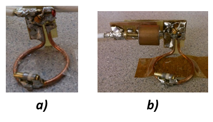
Loop coil: A 3cm loop coil was constructed and attached to a λ/2 cable (Figure 1a). The coil was tuned and matched to a phantom containing 2g/l NaCl2 and 1g/l CuSO4 solution. For comparison a balun was added adjacent to the matching network of the loop coil (Figure 1b).
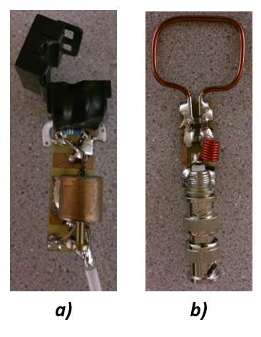
Common mode Measurement Probe: To measure the common mode voltages on the outside of a coaxial cable two windings of electrical wire were wrapped around a cylindrical ferrite housed in a split-able rectangular plastic shell. A 50Ω resistor was placed between the leads of the windings and connected to a coaxial cable balun to suppress common modes on the measuring coaxial cable line (Figure 2a).
Transfer-ratio coil: To characterize the transfer ratio of the measurement probe3 and calculate currents a rectangular loop coil was built (Figure 2b). The calibration loop coil was connected to a 50Ω port of a network analyzer (Rhode & Schwarz ZNC 3) set a 127.74 MHz sinusoidal output at 0dBm output power. The ferrite core setup was clamped over the conductor of the calibration loop coil and connected to an analog oscilloscope (Tektronix 2465B) terminated with 1MΩ AC coupling. Peak-to-peak voltage measurements were recorded on the oscilloscope for this setup.
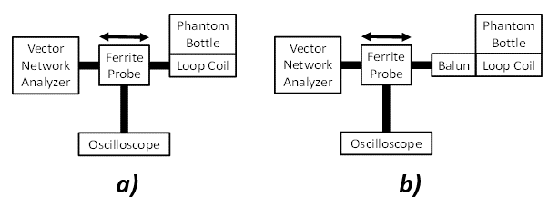
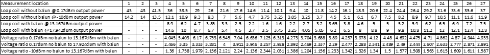
Common mode measurements: For common mode measurements the ferrite probe was clamped onto the coaxial cable of the loop coil and moved in 3.2cm increments (about the width of the ferrite). Peak-to-peak voltage measurements were taken for the loop coil without a balun (Figure 3a), using a network analyzer output power of 0.17dBm and -10dBm. A balun was then added to the coil (Figure 3b), and the measurements were repeated with 13.67dBm and 17.924dBm output power. The VNA output power was increased to keep the measured voltages within the sensitive range of the oscilloscope.
Results
Transfer-ratio coil: The reflection coefficient of the tuned transfer-ratio coil including the cylindrical measurement ferrite was measured at -27dB. At a -27dB reflection coefficient and 0.17dBm output power 99.8% of the power was transmitted into the coil equal to 643.71mV peak to peak voltage Vcpp and 12.87mA peak to peak current Icpp delivered into the loop. The measurement probe with the ferrite connected to the oscilloscope measured 350mV peak to peak voltage V50Ωpp. A transfer impedance Zt was calculated between V50Ωpp divided by Icpp of 27.2Ω or a transformation ratio of Vcpp between and V50Ωpp of 1.839:1.
Loop coil: The reflection coefficient of the loop coil without a balun varied between -20.9dB and 36.8dB depending on the location of the ferrite. It was stable and better than-24dB for all measurements with a balun.
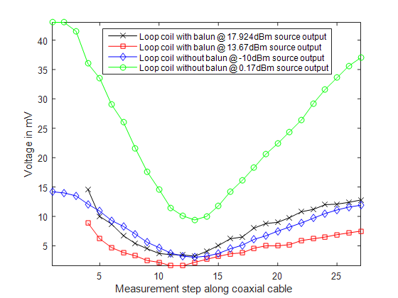
Common mode measurements in the loop coil: Common mode voltages were measured at 27 locations without and 24 with a balun along the coaxial cable. The values are plotted in Figure 4. To calculate the effective blocking of the balun the ratio of the common mode voltages measured with and without the balun were calculated, Table 1. The balun attenuation was found to be 29.06dB, 26.889dB, and 28.4dB for the three different sets of voltage conditions (giving an average attenuation of 28.1dB).
Conclusion and Discussion
A novel probe was used to measure common voltages along the coaxial cable of a loop coil and evaluate the performance of an in-line balun. The balun’s common mode attenuation was found to be on average 28.1dB. The measurement approach also allowed the field distribution along the outer coaxial conductor to be visualized which could aid the placement of additional baluns.Acknowledgements
No acknowledgement found.References
1. Balanis C. A. Antenna Theory Analysis and Design. 3rd Editon, John Wiley&Sons Inc., 2005.
2. Skelton R. Measuring HF Balun Performance. http://www.arrl.org/files/file/QEX_Next_Issue/Nov-Dec_2010/Skelton_QEX_Nov-Dec.pdf.
3. Wyatt K. The HF Current Probe: Theory and Application. https://interferencetechnology.com/the-hf-current-probe-theory-and-application/ . March 20 2012.
Figures