2652
The encoder as leading part of detecting torque on implants for a fully automated test method in accordance to ASTM F 2213 standard to improve MR-SafetyKarina Schuller1, Dominik Süß1, Manuel Stich1, and Ralf Ringler1
1X-Ray & Molecular Imaging Lab, OTH Amberg-Weiden, Weiden, Germany
Synopsis
Due to magnetically induced torque, strong magnetic fields cause different effects on medical devices like implants. In accordance to that, this study should investigate by the help of a rotary encoder, if a rotary movement can be acquired to the ASTM standard. The used rotary encoder is specified with a high angular resolution, which enables detailed rotating motion detection, and its MR compatibility.
Purpose
The ASTM F 22131 provides the standard for a manual measurement of the absolute angular deflection of the magnetically induced torque. A medical product is placed on a plate, which is stored by two springs. The magnetic field can induce a torque in the medical device, which also manifests as angular deflection at the plate. The absolute angular deflection is detected after a certain tuning phase. During the tuning phase oscillations occur with different frequencies and amplitudes. This is time-consuming and associated with recurring workflows within the magnetic field. An automation of this measuring method promises shorter measuring times as well as lower exposure times for the measuring staff. The aim of our work is to check whether it is possible to determine the absolute angular deflection by means of a rotary encoder, a special hardware and software, by means of continuous rotatory movement detection. Furthermore, the torque can be calculated using the extended measurement setup according to the ASTM standard1, whereby it must be ensured that the measuring results are not influenced by the magnetic field. Material & Methods
Using a motor and an adjustable disk, a defined oscillation (approx. 2.5 to 17 Hz) is generated at the encoder, similar to a steam locomotive (Fig. 1). With the help of the disc, different radii (2 to 14cm) are set, which lead to different angular deflections or amplitudes (approx. 13 to 95°) in the encoder signal. The output signal of the encoder is fed into the measuring card and evaluated using LabVIEW programming language. The measurement setup is tested with the same settings of radius and oscillation frequency in the magnetic field. The arithmetic mean-value for the amplitude of the encoder signal and the associated standard deviation with a defined radius, frequency and magnetic field setting are calculated every 100 oscillations. However, before the oscillating movements are simulated and recorded, the encoder is validated together with the software program. The encoder is installed directly to the axis of the motor. In addition to measurement using an encoder. An external speed measuring device is connected to the motor axis (Fig. 2). An angular output per time unit is used to acquire the speed at the encoder. The results are compared with the result of the speed measuring device. For both systems, the arithmetic mean value of 30 measurements as well as the associated standard deviation are calculated. Speeds from 120 to 1000 rpm are realized. A long-term test, which means that the motor rotates at constant speed for 30 minutes, is intended to show that the encoder produces stable results even during longer measuring periods. For the evaluation a 2-sample t-test with paired samples is carried out. In this case, the results of the encoder are compared in pairs with the corresponding value of the regression line, which is calculated from all the results of the encoder or with the result of the speed measuring device.Results
As expected, the resulting engine speed increased as the motor supply voltage increased. From the comparison of the rotational speed, determined by the encoder, with the results of the external speed measuring device, a higher standard deviation occurs with the speed measuring device compared to the encoder. In both systems, the standard deviation increases at higher speeds. From the paired t-test (α = 0.05) there is no significant difference between the two measurement methods at rotational speeds of approx. 7.9, 9.0 and 9.5 l/min. Furthermore, the encoder always measures reliably and correctly with a constant rotational movement (no significant difference, t-test with α = 0.05), taking into account the runtime effect on the motor. The amplitudes of a swinging motion are detected in the range of 2 to 14 cm for the radius as well as 2.1 to 16.5 Hz for the frequency of the encoder. The detection of a swinging motion with the encoder under the influence of a magnetic field shows no significant difference from the results without a magnetic field (t-test with α = 0.05).Discussion & Conclusion
The automated measurement of the torque according to the ASTM standard can be achieved with the selected encoder. The detection of the rotational movement during a torque examination in the magnetic field of an MRT is also possible with this encoder. The recording of a swinging motion can be performed with this selected experimental setup up to max. 16.5 Hz can be guaranteed. Higher frequencies lead to significant vibrations in the design, so measuring with the encoder is no longer possible. As a result, the plate for implant measurement according to the ASTM standard must not show any vibrations.Acknowledgements
No acknowledgement found.References
1. ASTM International. ASTM F 2213 – 06 (Reapproved 2011): Standard Test Method for Measurement of Magnetically Induced Torque on Medical Devices in the Magnetic Resonance Environment, 2011.Figures
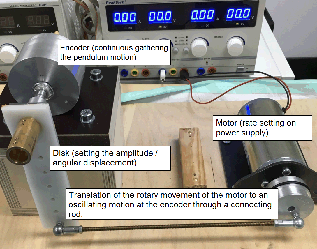
Fig. 1: Simulation of a defined oscillation movement (frequency and amplitude) at the encoder.
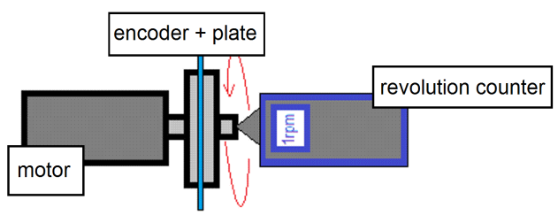
Fig. 2: Parallel measurement of a continuous rotational movement (rpm) by means of encoder and speed measuring device.