2649
Static Magnetic Field (B0) Gradient Evaluation of a Compact 3T MR Scanner1Radiology, Mayo Clinic, Rochester, MN, United States, 2GE Global Research, Niskayuna, NY, United States, 3GE Global Research
Synopsis
The strength of the static magnetic field produced by a MR system varies with the distance from the scanner. This generates a magnetic field spatial gradient (SG) which produces an attractive translational force on ferromagnetic objects that approach the system. Because the SG has bearing on patient safety related to implanted medical device, it is essential to understand the field distribution of novel magnets, since each design has its own unique SG pattern. We performed on-site evaluation of the magnetic field SG for a novel high-performance compact 3T MR scanner to ensure patient safety during the subsequent clinical trial.
INTRODUCTION
The strength of the static magnetic field produced by a MR system varies with the distance from the scanner. This generates a spatial gradient magnetic field that also varies with distance. The spatial gradient (SG) of the magnetic field produces an attractive translational force on ferromagnetic objects that approach the system. The force is linearly proportional to the product of the static field (at least up to a saturation value) and the SG. The US FDA places specific non-significant risk requirements for the static magnetic field, and field maps must be provided by MR scanner manufacturers1. Areas with fringe fields in excess of 0.5mT require controlled access. One aspect of the MRI-related labeling for implanted medical devices is to provide information about the highest SG magnetic field at which a particular device has been tested. The highest SG magnetic field on a conventional whole-body scanner is commonly located off-axis, at a sidewall, and near the opening of the bore of the scanner1,2. Because the SG has bearing on patient safety, it is essential to understand the field distribution of novel magnets intended for human use, since each magnet design has its own unique SG pattern.
A new, high-performance, compact 3T (C3T) MR scanner has been developed3-5. This system utilizes a conduction-cooled superconducting magnet which only requires less than 12liters of liquid helium, due to its reduced size (62cm warm bore) and novel cooling system. The magnet weighs only 1,900 kg, and measures 126cmx160cm. With gradient and RF coil inserted, the scanner’s patient aperture has 58 cm-diameter shoulder access, tapering to 37cm at isocenter, making it suitable for scanning heads, infants, and extremities. The 0.5mT fringe field is reported to be ~2x3m2 (radial /axial), compared to ~3x5m2 for a conventional whole-body 3T scanner. These unique characteristics of this magnet render the C3T scanner easy-to-site, and the installation at our institution did not require a vent stack. In this work, we perform on-site evaluation of the magnetic field SG for the C3T to ensure patient safety during the clinical trial.
METHOD
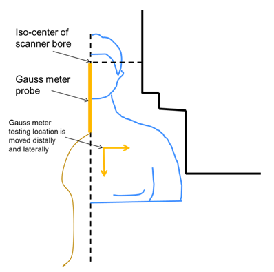
A magnetic field gauss meter (F.W.Bell, Milwaukie, OR) was used. Zero-field calibration was performed prior to each testing session. Initially the probe was placed at the isocenter of the scanner bore. The static field strength was measured along the x=y=0 iso-line with distance from isocenter increased in 10cm or 1cm step-by-step, depending on the gradient of the field. Then, the probe was laterally offset from iso-line at 5cm increments until the wall of the bore was reached. The field strength was recorded and the SG of the static field was calculated. The magnet field is assumed to be radially symmetrical about the iso-line, so the gradient along one radial line was measured.RESULTS
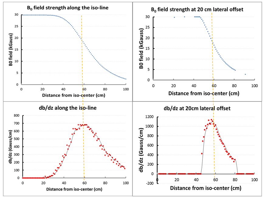
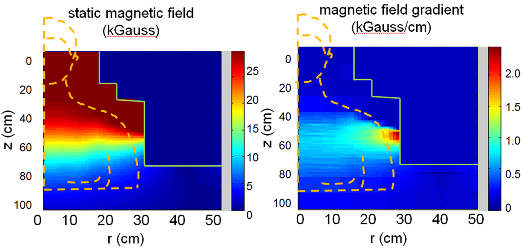
Figure 1 schematically shows the patient positioning inside of the C3T scanner and initial location of the gauss meter probe and the offset directions. Figure 2 shows the field strength of the B0 field and the spatial gradient. The highest gradient is found at the bore opening. The 2D field map and the static gradient map were plotted in Fig. 3. Some high SG hotspots (as high as ~20 T/m) can be appreciated around the shoulder cutout region of the bore.DISCUSSION/CONCLUSION
Uniform 3T field strength was measured inside of the bore. The field strength drops to approximately 0.5mT at z = 80 cm away from the isocenter, which is less than the patient table length. The C3T scanner produces a smaller fringe field footprint compared to conventional whole-body scanners, which reduces the room size and shielding requirement. Not surprisingly, the measured magnetic field is uniform in the central region and decreases rapidly near the opening of the magnet. The highest SG measurements are located near the wall of the patient bore, close to the shoulder region. As typical “MR Conditional” labeling may cite a limiting gradient of 7.2 T/m or 720 G/cm6, most of the magnet field satisfies such a criterion. As with other conventional whole-body scanners, the patient head would pass the SG<720G/cm zone without being exposed to the higher values. Care is still required from staff working on the scanner to prevent the implanted device from inadvertently transitioning through SG maxima. As commercially available whole-body magnets also have hotspots with SG>720 G/cm, these results indicate the SG of the C3T system is roughly comparable to actively shielded whole-body 3T systems. The results provided in this work may help to determine the risks for patients with MR conditional implants approaching the magnet.Acknowledgements
Funding Support: NIH R01EB010065References
1. American Society for Testing and Materials (ASTM) International. Designation F 2052-06e1: Standard Test Method for Measurement of Magnetically Induced Displacement Force on Passive Implants in the Magnetic Resonance Environment. West Conshohocken, PA: ASTM International; 2006.
2. Shellock FG, Kanal E, Gilk TB. Regarding the value reported for the term “spatial gradient magnetic field” and how this information is applied to labeling of medical implants and devices. Am J Roentgenol. 2011;196:1-4.
3. Weavers PT, Shu Y, Tao S, Huston J 3rd, Lee SK, Graziani D, Mathieu JB, Trzasko JD, Foo TK, Bernstein MA. Compact three-tesla magnetic resonance imager with high-performance gradients passes ACR image quality and acoustic noise tests. Med Phys. 2016 Mar;43(3):1259. doi: 10.1118/1.4941362.
4. Foo T, Tan ET, Schenck J, Graziani D, Laskaris ET, Vermilyea M, Sabourin C, Shu Y, Huston J, Bernstein MA. Novel High Performance, Compact 3.0T MRI System for Imaging the Brain. Military Health System Research Symposium (MHSRS), Orlando, FLA August 2016.
5. Lee SK, Mathieu JB, Graziani D, Piel J, Budesheim E, Fiveland E, Hardy CJ, Tan ET, Amm B, Foo TK, Bernstein MA, Huston J 3rd, Shu Y, Schenck JF. Peripheral nerve stimulation characteristics of an asymmetric head-only gradient coil compatible with a high-channel-count receiver array. Magn Reson Med. 2015 Dec 2. doi: 10.1002/mrm.26044.
6. Steckner MC, Frese G, van den Brink J, Schaefer DJ. Interpreting “spatial field gradient” MR conditional device labeling and the IEC 60601-2-33 3rd edition fringe-field compatibility technical specification sheet requirements. Proc Intl Soc Mag Reson Med. 2011;19:4658. Abstract 73.
Figures