2647
The Effect of Patient Orientation on Pacemaker Lead-Tip Heating at 1.5T1Department of Bioengineering, University of California, Los Angeles, CA, United States, 2Department of Radiological Sciences, University of California, Los Angeles, CA, United States
Synopsis
Patients with pacemakers or implantable cardioverter defibrillators (ICDs) may require an MRI exam of any body part. Clinical guidelines indicate that patient orientation in the scanner depends only on the body part under examination. Lead tip heating (LTH) is also a function of patient orientation. In this study our objective was to compare LTH for head-first and feet-first orientations for five pacemakers with realistic implant configuration in the ASTM torso phantom. Our results suggest that depending on the anatomical region examined, proper patient orientation in the MRI scanner can reduce LTH.
Introduction
Patient positioning in the MRI scanner is generally governed by the anatomical region being examined. Patients with pacemakers or implantable cardioverter defibrillators (ICDs) are not excluded from this guideline and patients with pacemakers may require an MRI exam of any body part. One principal concern is that the pacemaker may exhibit lead tip heating (LTH) during the scan that could damage tissues at the lead tip. Little is known, however, about the risks associated with LTH as a function of patient orientation (i.e. head-first vs. feet-first). Previous studies have demonstrated that the incident electric field (the driver of LTH) is axially asymmetric¹ in the ASTM torso phantom. An increased electric field magnitude is observed on the left-anterior and right-posterior aspect of the phantom. This suggests that patient orientation in the scanner will affect LTH. The objective of this work was to compare the LTH for head-first and feet-first orientations using realistic implant configurations in the ASTM phantom.Methods
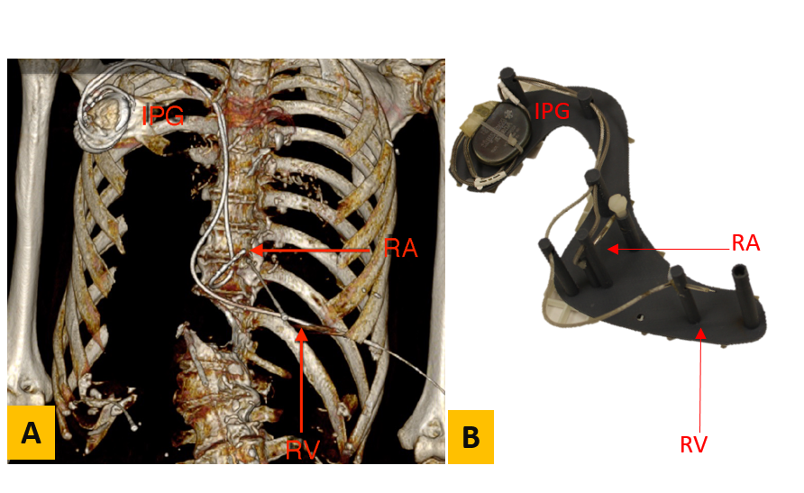
Experiments were performed for five different pacemakers (A to E) obtained from cadavers. Pacemakers A, C, and E were dual chamber, pacemakers B and D were single chamber. Pacemaker A was also in a right-sided implant location. CT scans were performed prior to pacemaker extraction (Fig. 1A). Using this data a support structure was 3D printed to enable placement of each implanted pulse generator (IPG) and lead in an ASTM torso phantom matched to the implant geometry (Fig. 1B). Pacemaker-A was placed on the right side of the phantom, while Pacemakers-B to E were placed on the left side in accordance with the implant location. The phantom was filled with polyacrylic acid with an electrical conductivity of 0.48 S/m and exposed to 4 W/kg SAR using a turbo spin echo sequence (TE/TR = 6.2/110ms, Flip Angle=180) for 5 minutes at 1.5T (Siemens Avanto Fit) for both head-first (HF) and feet-first (FF) orientations. The temperature increase (∆T) at one or both lead tips was recorded for nine different landmarks (LM) at isocenter using a fiber optic temperature probe. LM1 corresponded to the center of the phantom’s head and LM2-LM9 were placed at 9cm intervals increasingly in the inferior direction.Results
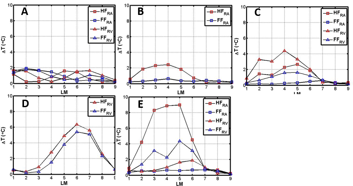
Fig. 2 shows that ∆T depends on both the lead path and phantom orientation. For the Pacemaker A (positioned on the right side) ∆T at LM1 to LM4 was greater for FF than HF while the opposite was true for LM5 to LM6 (Fig. 2A); heating did not exceed 2C. For the pacemakers positioned on the left side (Fig. 2B to E), ∆T was greater at LM2 to LM6 for HF compared to FF.Discussion
In a clinical setting, patients are placed in the MRI scanner depending on the body part under examination with no regard for pacemaker position. In current clinical practice HF examinations are performed for neuroimaging (LM1) and cardiac scans (LM2-LM4). The FF approach is utilized for imaging of the lower extremities while abdominal (LM5-LM6) and pelvic (LM7-LM9) examinations can be performed using either orientation. The results obtained in this study suggest that for left sided pacemakers, LTH for thoracic or abdominal scans (between LM2 and LM6) could be minimized in a FF orientation. While previous studies have demonstrated that LTH depends on pacemaker geometry², we have found that patient orientation also influences LTH. This suggests that special consideration should be given to patient orientation for patients with pacemakers in order to minimize LTH.Acknowledgements
Funding support from the Department of Radiological Sciences and NIH R21 HL127433.References
1. Nordbeck, P. et al. Spatial distribution of RF-induced E-fields and implant heating in MRI. Magn. Reson. Med. 60, 312–319 (2008).
2.Calcagnini, G. et al. In vitro investigation of pacemaker lead heating induced by magnetic resonance imaging: Role of implant geometry. J. Magn. Reson. Imaging 28, 879–886 (2008).
Figures