2646
Comparison of Pacemaker Lead Tip Heating at 1.5 T and 3T1Department of Bioengineering, University of California, Los Angeles, CA, United States, 2Department of Radiological Sciences, University of California, Los Angeles, CA, United States
Synopsis
Imaging patients with pacemakers at magnetic fields higher than 1.5T is widely contraindicated due to safety concerns. Since SAR increases with B₀² it is expected that lead tip heating (LTH) may increase substantially. Recent studies, however, provide evidence that contradicts this belief. Electromagnetic damping can occur in highly conductive materials at high field strengths and may result in lower LTH. Our objective was to compare LTH at 1.5T and 3T for five pacemakers with realistic implant configuration in the ASTM torso phantom. The results obtained showed that heating at 3T was not greater than 1.5T, which supports the argument that electromagnetic damping can result in lower LTH at higher field strengths.
Introduction
MRI exams for patients with pacemakers and implantable cardioverter defibrillators (ICDs) are generally contraindicated particularly at field strengths above 1.5T. One concern is the B₀ magnetic field interaction with the device, which may cause device malfunction or movement¹. Increased lead tip heating (LTH) at higher fields is also a concern that arises due to the fact that SAR is proportional to the square of the B₀ field strength. At higher fields the resonance frequency increases, but the incident electromagnetic (EM) wavelength decreases². In high conductive materials, electromagnetic damping arises due to destructive interference caused by the interactions between the induced electric field and the reflected electric fields at the lead, resulting in decreased LTH. Consequently, it remains unclear if LTH is increased or decreased at higher field strengths. Therefore, the objective of this work was to compare LTH at 1.5T and 3T using realistic implant configurations in the ASTM phantom.Methods
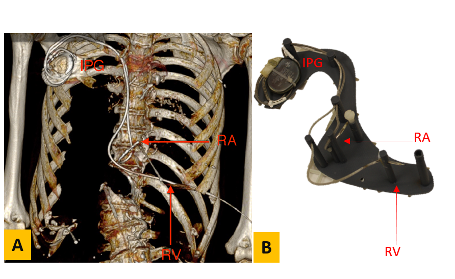
Experiments were performed for five different pacemakers (A-E) obtained from cadavers. Pacemakers A, C, and E were dual chamber, while pacemakers B and D were single chamber. CT scans of cadavers were performed prior to pacemaker extraction (Fig. 1-A) and used to design a 3D-printed support structure that enabled placement of each implanted pulse generator (IPG) and lead in an ASTM torso phantom matching the original implant geometry (Fig. 1B). Pacemaker-A was placed on the right side of the phantom, while pacemakers-B to E were placed on the left side in accordance with the original cadaver implant location. The phantom was filled with polyacrylic acid with an electrical conductivity of 0.48 S/m exposed to 4 W/kg SAR for 5 minutes at 1.5T (Siemens Avanto fit) and at 3T (Siemens Prisma) using a turbo spin echo sequence. The temperature increase (∆T) at one or both lead tips was recorded using a fiber optic temperature probe for nine different landmarks (LM) at isocenter. LM1 corresponded to the center of the phantom’s head and LM2-LM9 were placed at 9cm intervals in the inferior direction.Results
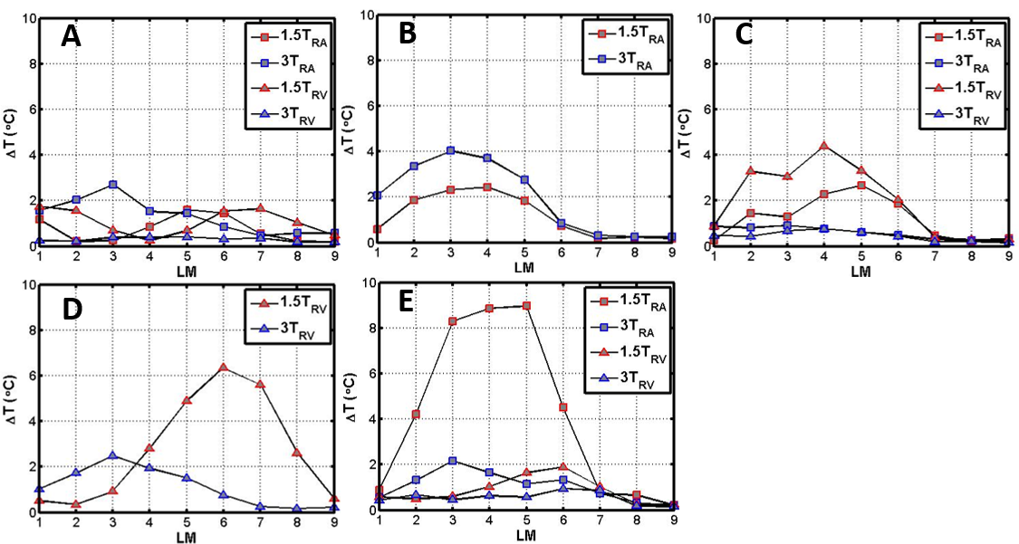
Fig. 2 shows ∆T values for each pacemaker. For pacemakers A and B (Fig. 2A-B), the largest ∆T was observed at 3T for the right atrial (RA) lead. However, it did not increase more than 4°C. Pacemakers C to E showed a greater ∆T at 1.5T compared with 3T. Maximum heating occurred between LM3-LM5 except for pacemaker D (Fig. 2D) in which the maximum was at LM6.Discussion
Given that SAR is proportional to the square of the B₀ field strength, it nominally increases by a factor of four in the 3T scan relative to the 1.5T scan. Since ∆T is proportional to SAR, this suggests that ∆T should be greater in the 3T scans. This logic, however, ignores frequency and wavelength effects. Our results demonstrate that LTH at 1.5T can exceed that seen at 3T. This could be due to deconstructive interference induced by electromagnetic damping which is caused by the interactions between the induced electric wave and electric waves reflected by the lead as shown by Yang et al³. Further studies are needed in order to evaluate safety for different lead lengths and device placements. Importantly, the precise E-field exposure along the lead for each experiment was not measured. Future studies would benefit from having this information available.Acknowledgements
Funding support from the Department of Radiological Sciences and NIH R21 HL127433.References
1. Shellock, F. G. (2014 ). 3-Tesla MR Safety Information for Implants and Devices.Reference Manual for Magnetic Resonance Safety, Implants and Devices: (pp. 180-184). Biomedical Research Publishing Group. 2.Collins, C. M., Liu, W., Schreiber, W., Yang, Q. X. & Smith, M. B. Central brightening due to constructive interference with, without, and despite dielectric resonance. J. Magn. Reson. Imaging 21, 192–196 (2005). 3.Yang, Q. X. et al. Analysis of wave behavior in lossy dielectric samples at high field. Magn. Reson. Med. 47, 982–989 (2002). 8).
Figures