2638
A Raspberry Pi® Based Portable Exposure Monitoring System for Magnetic Fields up to 7T.1Otto Diels Institute for Organic Chemistry, Kiel University, Kiel, Germany, 2Molecular Imaging North Competence Center, University Medical Center Schleswig-Holstein, Kiel, Germany
Synopsis
ICNIRP recommends reference values for movements in magnetic fringe fields of MRI systems. Several probes have been presented using custom interfaces to record data. To open this field of research to a wider public a Raspberry Pi® based magnetic field monitoring system was built. A probe consisting of both three Hall sensors and induction coils was used. All channels were converted into frequency via voltage-to-frequency-converters. Data was stored internally via python. Measurements were performed on a 7T small-animal MRI at the hand of MR-workers. Reference values were exceeded at the hand. No transient effects like vertigo or nausea were noticed.
Introduction & Purpose
The new International Commission on Non-Ionizing Radiation Protection (ICNIRP) guidelines recommend reference levels of 2.7 T/s for movement in the magnetic fringe field of an MRI system1 to avoid transient effects like vertigo, nausea2 or magnetophosphenes3. Long term effects are still unknown. Several magnetic field probes have been presented to record the magnetic field exposure of MR personnel and patients4,5. For everyday use a portable monitoring unit with a custom built data logging circuit was introduced6.
To open this field of research to a wider public a Raspberry Pi® based magetic field monitoring system is presented in this study which can be used in the environment of an MRI system up to 7T to record the daily magnetic field exposure of MR personnel.
Methods
A small magnetic field probe with both three orthogonal induction coils and Hall sensors was used in this study. The probe itself was used from a former project6. The Hall sensors and the induction coils (500 windings, coil area: 5 mm2) were attached to an acrylic glass former with 10 mm edge length (Fig. 1). Six zero-drift low-noise amplifiers (LTC 1050, Linear Technology Corp., Milpitas, USA) were used to amplify both input voltages from induction coils and Hall sensors. The probe was connected to the main unit by a 1.5 m long signal cable. Six voltage-to-frequency converters (LM331, Texas Instruments Corp., Dallas, USA) were used to convert the amplified analog voltages into specific frequencies and were fed into a separate general purpose input output (GPIO) port. A Raspberry Pi (Model B+, Raspberry Pi Foundation, Cambridge, England) was used to record the converted voltages with the in-built python environment (Version 2.7.9, Python Software Foundation). Most ferromagnetic components of the Raspberry Pi (e.g. camera port, unneeded USB port) were removed or substituted by non-magnetic parts (e.g. inductors at the power input). A non-magnetic rechargeable power supply was used. Data was stored on the internal SD-card. After each exposure measurement a separate file was saved. After completing all measurements all files were copied from the Raspberry Pi via USB. Data was analyzed on a standard PC with spreadsheet processing software. The system was calibrated using same methods as in former studies4,6.
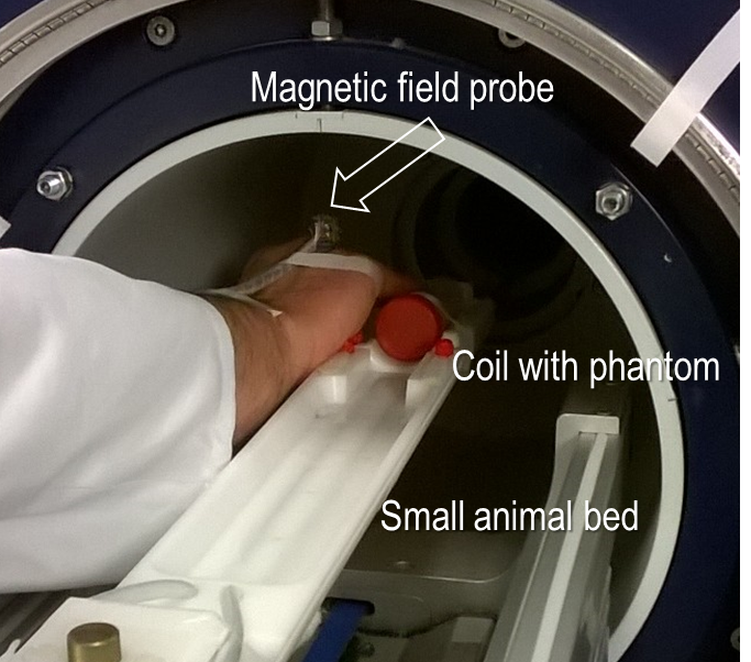
Exposure measurements were performed in the magnetic fringe field of a 7 Tesla small animal MRI system (ClinScan 7T 70/30, Bruker Biospin, Ettlingen, Germany). Due to the small magnetic footprint of the MRI system the probe was worn at the hand to demonstrate the capacity of the monitoring system (Fig. 2). Three exposure parameters, the magnitude of the magnetic flux density (B0), the magnitude of time derivative magnetic flux density (from B0; dB/dttrans) and the magnitude of the time derivative magnetic flux density (from induction coils; dB/dtrot+trans) were recorded simultaneously.
Results
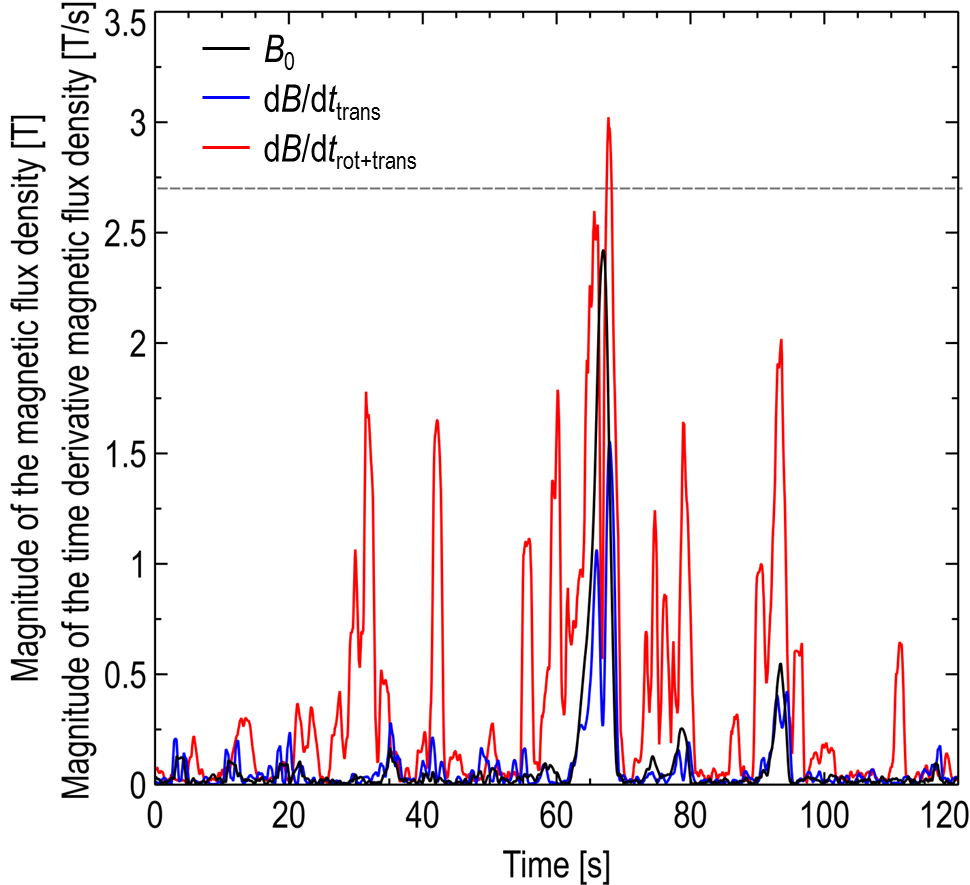
During seven exposure measurements maximum peak values of B0, dB/dttrans and dB/dtrot+trans of 2.42 T, 1.55 T/s and 3.02 T/s were recorded. Figure 3 shows exemplary data of a phantom placement procedure at the bore of a 7T small animal MRI system. Due to the sampling rate (16 samples per second per channel) of the GPIOs also fast changes in in low magnetic fields outside the bore can be securely detected (peaks of dB/dtrot+trans in Fig. 3).
Discussion & Conlusion
The recorded exposure data exceeded the recommended reference levels only at the hand of the MR-workers. It is assumed that the reference value for exposure is not exceeded at the head since no transient effects like vertigo or nausea were noticed during all measurements. In whole-body ultra-high field MRI systems up to 7 Tesla the probe will be worn at the head position in following experiments. In future the Raspberry Pi B+ will be substituted by a Raspberry Pi A+ or Zero due to lower power consumption (4 W [B+] vs 1.2 W [A+] or 0.7 W [Zero]).
Acknowledgements
No acknowledgement found.References
1. International Commission on Non-Ionizing Radiation Protection (ICNIRP). Guidelines for Limiting Exposure to Electric Fields Induced by Movement of the Human Body in a Static Magnetic Field and by Time-Varying Magnetic Fields below 1 Hz. Health Phys 2014;106(3):418-425.
2. Glover PM, Cavin ID, Qian W, Bowtell RW, Gowland PA. Magnetic-Field-Induced Vertigo: A Theoretical and Experimental Investigation. Bioelectromagnetics 2007;28:349-361.
3. Weintraub MI, Khoury A, Cole SP. Biologic Effects of 3 Tesla (T) MR Imaging Comparing Traditional 1.5 T and 0.6 T in 1023 Consecutive Outpatients. J Neuroimaging 2007;17(3):241-245.
4. Groebner J, Umathum R, Bock M, Krafft, AJ, Semmler W, Rauschenberg J. MR Safety: Simultaneous B0, dΦ/dt, and dB/dt Measurements on MR-Workers up to 7 T. Magn Reson Mater Phy 2011;24(6):315-322.
5. Kännälä S, Toivo T, Alanko T, Jokela K. Occupational Exposure Measurements of Static and Pulsed Gradient Magnetic Fields in the Vicinity of MRI Scanners. Phys Med Biol 2009;54(7):2243-2257
6. Groebner J, Umathum R, Bock M. A Portable MR Exposure Monitoring System for B0 and dB/dt up to 7T. Proc Intl Soc Mag Reson Med 2013;2821
Figures
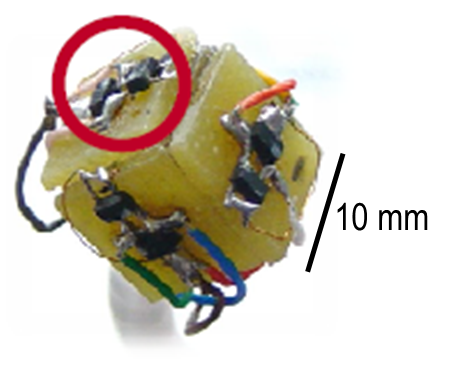
Figure 1: Close-up view of the magnetic field probe consisting of three Hall sensors (circle) and three induction coils (on holder underneath).