2637
Magnetically Induced Torque Assessment per ASTM F2213 of Active Implantable Medical Device Lead Materials1St. Jude Medical, Sylmar, CA, United States
Synopsis
This abstract presents magnetically induced torque measurements (per ASTM F2213) of materials commonly used in implantable leads. Implantable leads which are constructed solely from tested materials which pass the magnetically induced torque testing acceptance criteria of gravity torque, may not require magnetically induced torque testing per ASTM F2213 for MR conditionality with 3 T MR scanners.
Purpose
The assessment of MR safety, or MR conditional safety, of medical device implants rely on a number of standard test methods. ASTM F2213, the magnetically induced torque test method, is one of the methods required as part of MR safety testing. The purpose of this study was to evaluate the magnetically induced torque of individual materials typically comprising implantable leads. For leads that are constructed solely from materials that pass the magnetically induced torque testing acceptance criteria (i.e. gravity torque), the results of this study may eliminate the need to measure these leads’ magnetic torque per ASTM F2213.
Methods
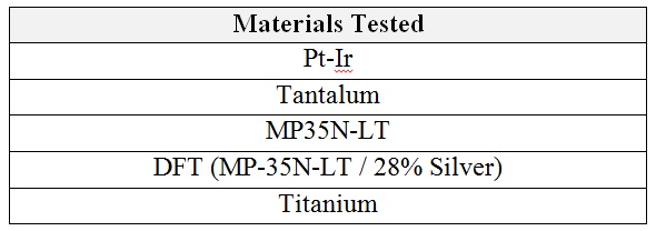
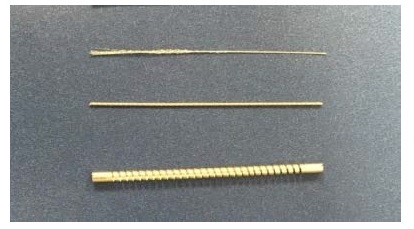
The static magnetic field associated with a magnetic resonance system (MR) produces a torque on a device/material that acts to align the long axis of the object with the magnetic field. To evaluate this magnetically induced torque, ASTM F2213 includes both qualitative and quantitative assessments for characterizing magnetically induced torque. In this study, the qualitative low friction surface method was used in a Siemens Magnetom Prisma (3T) MR scanner for each of the commonly used lead materials shown in Table 1. Each lead material was prepared by trimming the lead sample material to a length of two (2) inches as shown in Figure 1. This length was chosen as it is more than two times (2x) the longest expected distal ridged length of any implantable medical device lead where torque could be transferred.
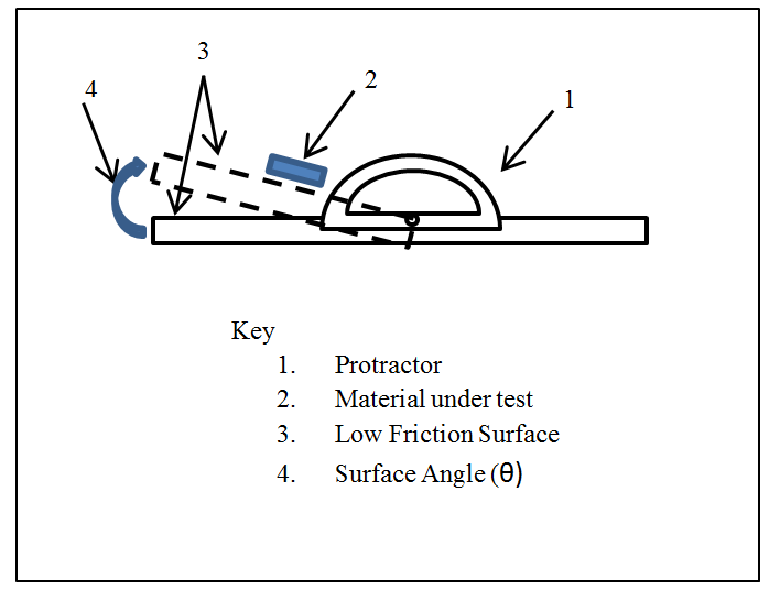
For the low friction surface method, the coefficient of friction between the test sample and the low friction surface is first evaluated (outside of the MR field) to ensure that the frictional force between the device and the low friction surface is less than or equal to the weight of the device. This is accomplished by tilting the low friction surface (see Figure 2) to an angle at which the device is on the verge of sliding and then measuring this angle. If the measured angle is less than 45° than the frictional force between the device and the low friction surface is less than the weight of the device.
Testing is then performed in a MR scanner. The low friction surface is positioned at the isocenter of a MR scanner and the test sample is laid flat on the low friction surface. Visual verification is then used to ensure that the sample does not move or rotate to align with the magnetic field of the scanner. The test sample is then rotated about isocenter (on the xz plane) in 45° angle increments until a 360° rotation has been completed. At each angle increment, visual verification is used to ensure that the device does not move or rotate to align with the magnetic field of the scanner. If no motion is observed and the device remained static, then the magnetically induced torque is less than the cross product of the friction force (between the device and the low friction surface) and the length of the device.
Per ASTM F2213, the maximum MR induced torque exerted on the test samples by the static magnetic field should be compared to the gravity torque exerted by the earth on the sample, defined as the product of the maximum linear dimension of the device and its weight. If a test sample has a frictional force that is less than the weight of the test sample (i.e. θ<45°) and the test sample does not move or rotate to align with the magnetic field of the scanner during testing, then that test sample has a MR induced torque that is less than gravity torque.
Results
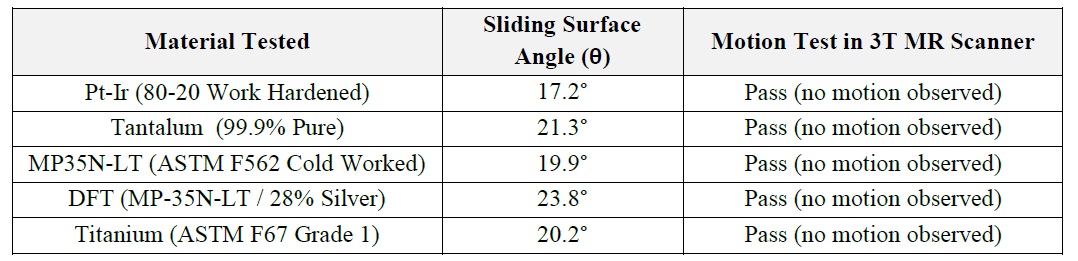
As can be seen in Table 2, all five (5) of the commonly used lead materials which were tested in a 3T MR scanner using the qualitative low friction surface method per ASTM F2213 had a MR induced torque that was less than gravity torque (defined as the product of the maximum linear dimension of the device and its weight).Discussion and Conclusions
Our results demonstrate that the commonly used lead materials tested, when exposed to a 3T MR scanner, exhibit a maximum magnetically induced torque that is less than gravity torque. As such, implantable leads that are constructed solely from these materials will also pass this magnetically induced torque testing requirements, and therefore may not require magnetically induced torque testing per ASTM F2213 for MR conditionality with MR scanners having a magnetic field strength up to 3T.Acknowledgements
No acknowledgement found.References
1. ASTM Standard F2213, 2015 Standards Committee Draft, "Standard Test Method for Measurement of Magnetically Induced Torque on Medical Devices on the Magnetic Resonance Environment," ASTM International, West Conshohocken, PA, www.astm.org
2. Nyenhuis et. al, MRI and Implanted Medical Devices: Basic Interactions with an Emphasis on Heating, IEEE T-DMR 5(3), 467-80
3. Childers et. al, Magnetically Induced Force Measurements per ASTM F2052 of Active Implantable Medical Device Lead Materials, Poster session presented at 24th Annual Meeting of the International Society for Magnetic Resonance in Medicine, 2016 May 7-13; Singapore
Figures