2636
Safety of intracranial EEG recordings at 1.5T MR: electromagnetic field simulation on a human body model1Center for Biomedical Imaging (CIBM), Ecole Polytechnique Fédérale de Lausanne (EPFL), Lausanne, Switzerland, 2Department of Clinical and Experimental Epilepsy, UCL Institute of Neurology, London, United Kingdom, 3Laboratory of Functional and Metabolic Imaging, Ecole Polytechnique Fédérale de Laussanne (EPFL), Lausanne, Switzerland, 4Developmental Imaging and Biophysics Section, UCL Institute of Child Health, London, United Kingdom, 5Departments of Radiology, University of Lausanne and Geneva, Lausanne and Geneva, Switzerland
Synopsis
Excessive tissue heating is one of the major concerns when performing MRI in patients with icEEG due to the RF interaction between the electrodes and head tissue. No electromagnetic field simulations has been performed on in-vivo iEEG-MR setup due to the subgridding limitations of the small dimensions of these electrodes relative to those of the human body. We showed the feasibility of full body EM-field simulations based on realistic icEEG-electrode design. The proposed FDTD method for simultaneous icEEG-MRI gives results that are in broad agreement with previous experimental observations while allowing for measurements of SAR/heating along the entire implant length.
Introduction
Excessive tissue heating is one of the major concerns
when performing MRI in patients with intracranial electroencephalography (icEEG)
due to the radiofrequency (RF) interaction between the electrodes and head
tissue1. Up to now, the amount of heating caused by MR scanning has
been estimated theoretically and experimentally by local temperature probe
measurements on homogeneous phantoms2-4, providing incomplete information
on the interactions between the RF field and tissue in the presence of icEEG
electrodes. There is therefore a need for realistic electromagnetic field (EM-field)
simulations. The purpose of this study is to demonstrate the feasibility of
full body EM-field simulations based on realistic icEEG electrode design to
estimate tissue heating variation for simultaneous icEEG-MRI.Methods
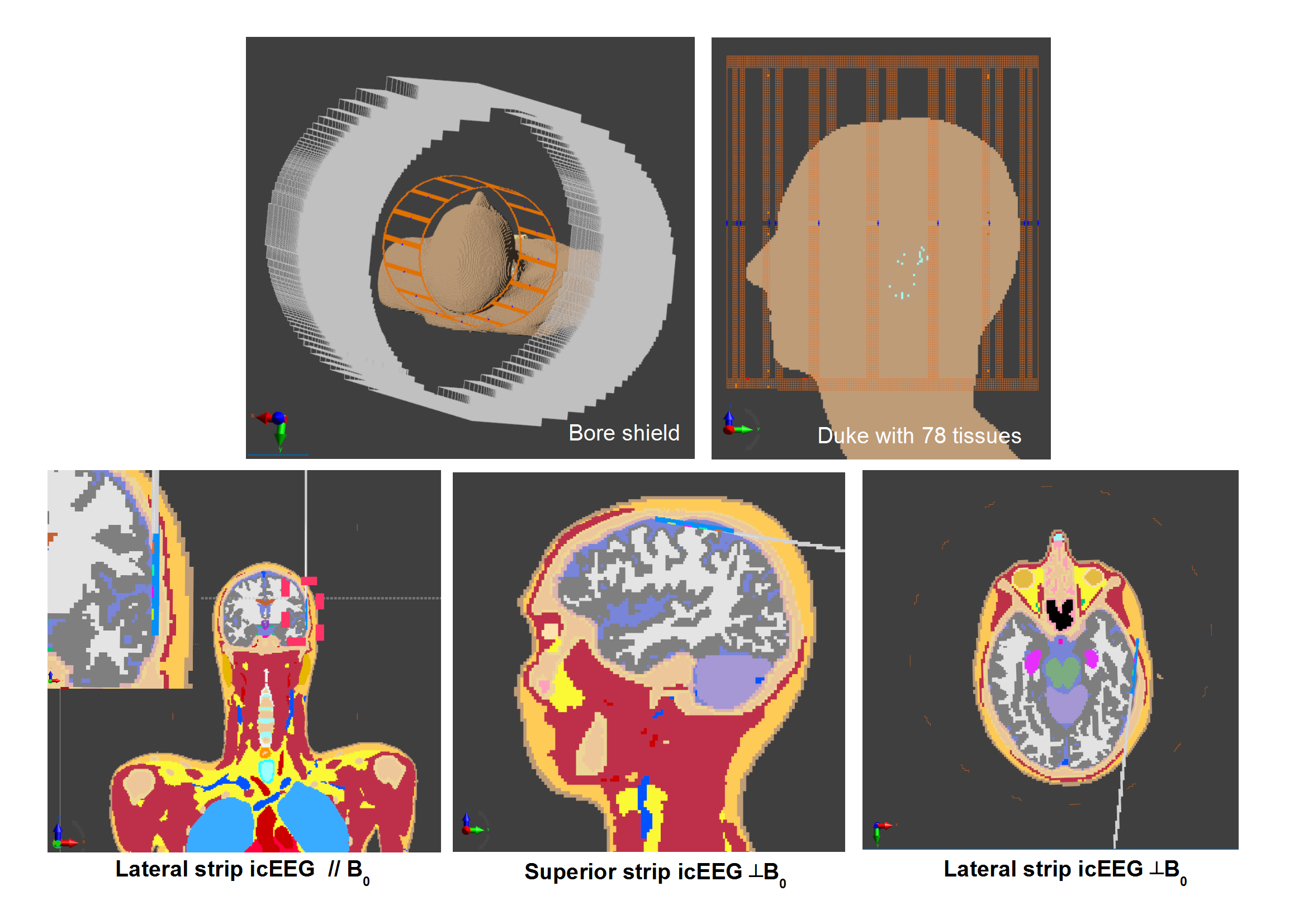
Finite Difference Time Method (FDTD) simulations were performed on Duke (34-year old male from the Virtual Family5) with 78 different tissue types using Sim4Life 3.1 (ZMT, Switzerland) to evaluate the RF field interaction of a depth icEEG electrode (Ad-Tech, Racine, WI) with a head birdcage RF coil. Experimentally measured B1+ maps on a healthy volunteer, and simulated SAR maps in three different icEEG configurations were obtained.
A Low-pass head birdcage coil (Fig.1)(diameter: 13.5cm, length= 27 cm, 16 legs modeled as perfect electric conductor (PEC), C=6.65 pF, two-channel quadrature-driven) with the bore shield (diameter= 30 cm, PEC) was simulated and the circularly-polarized mode was excited. The coil and Duke were oriented along B0 field (z-axis). The simulation model was meshed in a non-uniform grid of approximately 34 MCells, with voxel steps ranging from 0.18x0.42x0.8 mm3 to 287x308x178 mm3. Perfectly matched layers of medium strength were used at the edges of simulation domain. A harmonic excitation at 64 MHz was applied, and steady-state conditions (convergence level: 50 dB) were achieved within 50 simulation cycles. The simulation time was ~8 hours/channel with the CUDA solver.
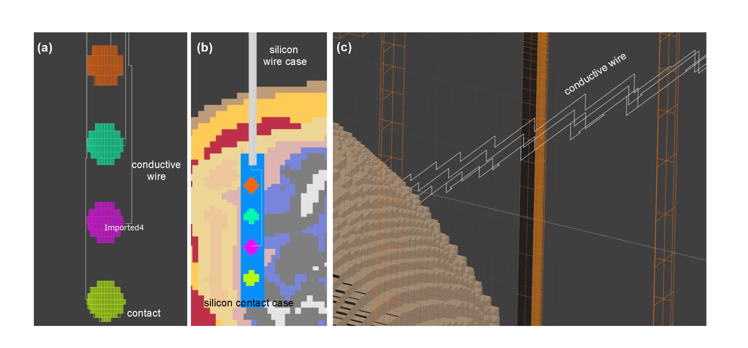
Strip icEEG electrodes (Fig.2) with four contacts, longitudinally aligned and 10 mm apart were designed on Solidworks (Dassault Systemes, France) and imported into Sim4Life. The electrodes consist of 4 mm diameter platinum PEC disc contacts (2.3 mm of which is exposed to tissue) imbedded within a silicon contact case and connected by nickel-chromium PEC wires (length: 250 mm) in polyurethane tubing. The electrodes were placed in three different locations on the brain’s surface (Fig.1) while insuring good contact between the iEEG contacts and brain parenchyma. The icEEG components were voxelized as having higher priorities (contacts:20, wires:20, contacts silicon case: 10, silicon tube:10) than the Duke tissues (priority:0).
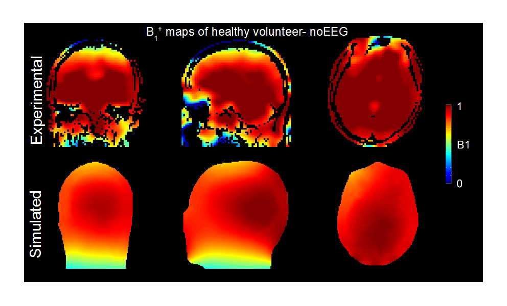
Experimental B1 maps were acquired using the Double-Angle method6 on a 1.5 MR scanner (Avanto, Siemens Healthcare, Germany) on a healthy volunteer using the transmit-receive head RF coil and analysed using Matlab (Mathworks, USA) for comparison with the simulation results.
Results & Discussions
Figure
3 shows a good agreement between the experimental and simulated B1+
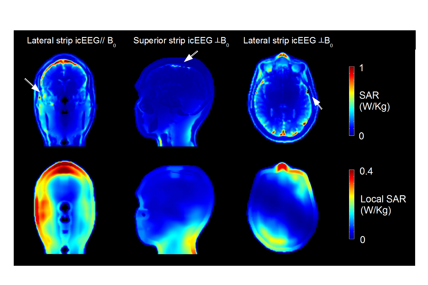
maps in each plane. Simulations showed that the positioning of lateral
icEEG electrode parallel to B0 resulted in 10g-averaged SARMAX
being 20% higher than the value without any icEEG electrodes or lateral icEEG
electrodes placed perpendicularly to B0 (Fig.4). It may indicate
that the orientation of the conductive wires with the lateral iEEG contacts has
an influence on the tissue heating for the lateral icEEG. Moreover, the superior
icEEG strip contacts placed perpendicular to B0 resulted in the greatest
local SAR increase (~60% compared to a birdcage only) (Fig.4).Conclusion
The proposed FDTD electromagnetic field simulation method for simultaneous icEEG-MRI gives results that are in broad agreement with previous experimental observations while allowing for measurements of SAR/heating along the entire implant length. Non-uniform conformal voxeling enables the simulation of a fully-detailed realistic in-vivo icEEG-MR setup.Acknowledgements
Supported by Centre d’Imagerie Biomedicale (CIBM) of the UNIL, UNIGE, HUG, CHUV, EPFL, the Leenards and Jeantet Foundations.References
1. Lemieux L. et al. ., Magn. Reson. Med. 38 (1997) 943-957.
2. Carmichael, D.W. et al., Neiroimage 49 (2010)379-390.
3. Carmichael D. W. et al., Neuroimage 63 (2012) 301-309.
4. Boucousis S.M. et al., Neuroimage 63 (2012) 1237-1248.
5. Gosselin MC et al., Phys Med Biol 2014 ; 59(18) : 5287-5303.
6. Stollberger R. et al., Proc. SMRM ( 1988), p. 106.
Figures