2635
Attenuation of RF-induced currents within neuro-stimulation leads using a helical conductor design1Systems Engineering, Nuvectra Medical, Broomfield, CO, United States, 2R&D, Nuvectra Medical, Broomfield, CO, United States, 3R&D, Medical Technology Labs, La Mirada, CA, United States
Synopsis
RF currents will be induced within implanted neuro-stimulation leads when exposed to Magnetic Resonance Imaging (MRI) fields. Induced currents result in dissipative heating that manifests at the electrode/patient contact points. The ideal lead design will attenuate induced 64-MHz RF energy coming from the MRI while passing signals in the lower, intended neuro-stimulation frequency range. A Nuvectra™ SCS lead, having a helical conductor coiling design, is evaluated. Results of MRI phantom experiments demonstrate RF-induced power attenuation between -6.2 and -12.5 dB/meter when exposed to combined fields from 1.5 Tesla, 2.77 W/kg for minutes.
Purpose
The ideal stimulation lead design will attenuate induced 64-MHz RF energy coming from the MRI while passing signals in the lower, intended neuro-stimulation frequency range. The purpose of the experiment described herein is to characterize the signal attenuation of a helical 8 electrode stimulation lead design at the MRI RF induced frequency of 64 MHz.Methods
RF current (at and above 64 Mhz1) will be induced into implanted stimulation leads that are positioned in regions where the E-field generated by a Magnetic Resonance Imager (MRI) is strongest and is tangentially oriented. The induced energy dissipates as heat that manifests at the electrode/patient contact points. Measurement of the electrode temperature provides a reliable means to approximate the amount of current flowing in the lead.2
The portion of the stimulation lead primarily travelling within the central axis of the MRI does not pick up much induced current because of the low E-field in that area. Lead length along the central axis (which is the typical clinical placement for Spinal Cord Stimulation therapy) serves to attenuate a portion of the energy that is induced in the high E-field regions.
Multiple SCS lead pathway configurations with varying distal segment lead lengths, H2, were exposed to MRI scans within a gel phantom. See Figure 1. Electrode temperatures corresponding to each configuration were measured using MRI-safe fiber optic probes. "Attenuation" was defined as the ratio of measured electrode temperatures between any two similar configurations. The attenuation-per-unit length of distal lead segment was determined by dividing the attenuation by the change of distal length.
Results
The attenuation for the distal lead portion was shown to range from -0.58 dB to -6.43 dB for incremental lengths ranging from 5 to 29 cm. The attenuation-per-unit-length for the three cases had an average value of -15 dB/m. See Table 1.
Discussion
Attenuation of RF energy, by the lead, is consistent with the theory for power transfer between a transmission source and load. The lead corresponds to the transmission line and the load is the human body tissue (or gel phantom).
The lead’s distributed parasitics can be lumped sum modelled as an LCR equivalent circuit. Further simplification is obtained by assuming that the effects of resistance and capacitance at the MRI RF range are negligible. The simplified lead impedance is given by $$$Z_{S}=j2\pi f L_{S}$$$ where ZS is the lead's source impedance, LS is the inductance of the lead, and f is the frequency of the induced RF. The RF power that transfers to the body (in the form of heat) is given by the following formula:
$$P_{B}=\frac{|V|^{2}R_{B}}{2(R_B^2 + Z_S^2)}$$
where RB is the body impedance and PB is the power dissipated into the body or phantom.
The inductance of the lead is a function of length. For a helical coiling of wire, the inductance-per-unit-length is given by the following equation3:
$$\gamma_{L}=\frac{dL}{dx}=\frac{\mu_{o}\cdot K\cdot\pi \cdot D^{2}}{4\cdot Pitch^{2}}$$
where,
$$$\gamma_{L}$$$ is the inductance per unit length,
$$$\mu_{o}$$$ is the permeability of free space,
K is the Nagaoka coefficient, D is the helical diameter, and
Pitch is the pitch of the helical.
The Nuvectra™ leads evaluated in the experiment all have a multi-conductor inner helical winding of D=0.020" and inner pitch is .019". Bench measurement were 3.0 uH/m compared to 3.3 uH/m based on formula with K=3. The parasitic resistance of the lead was also measured for reference. The per-unit-length resistance has values of 45 ohms/m which is 1/10 the measured body (or, gel phantom) load resistance. This partially confirms the validity of applying a simplified lead impedance model for estimating attenuation.
The attenuation effect is the ratio of the predicted power for one lead length to the power of another lead length. It is a function of lead length is derived by combining the previous formulas resulting in the following:
$$A(x)\approx\frac{R_B^2}{R_B^2 + (2\pi f \gamma_{L} x)^2}$$
where A(x) is the attenuation factor as a function of distal lead length x.
The theoretical attenuation for each lead configuration that was measured in the gel phantom under MRI exposure was calculated. The results are provided in graph form in Figure 2.
Conclusion
The amount of electrode heating measured under MRI RF exposures for multiple distal lead segment length configurations confirmed an attenuation effect on the order of -12 dB per meter of length lying in the central axis. The attenuation effect experimentally observed correlates with the predicted RF-induced power transfer through an inductive lead to a resistive body tissue load. The mean error between measured and predicted for the five length variations examined was 8%.
Acknowledgements
No acknowledgement found.References
1. Simunic, Dina, et al. "Spatial distribution of high-frequency electromagnetic energy in human head during MRI: numerical results and measurements." IEEE transactions on biomedical engineering 43.1 (1996): 88.2. ASTM F2182–09. Standard test method for measurement of radio frequency induced heating near passive implants during magnetic resonance imaging. West Conshohocken, PA: ASTM International 2009.
3. Nagaoka, Hantaro (1909-05-06). "The Inductance Coefficients of Solenoids" (PDF). 27. Journal of the College of Science, Imperial University, Tokyo, Japan: 18. Retrieved 2011-11-10.
Figures
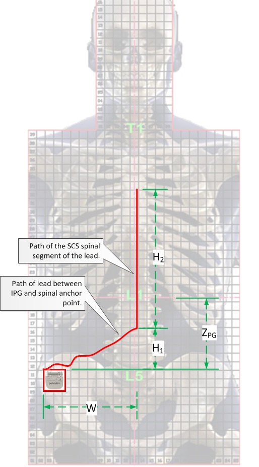
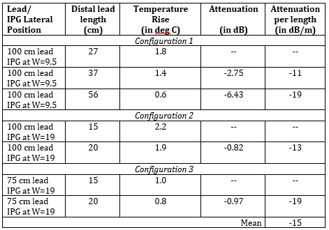
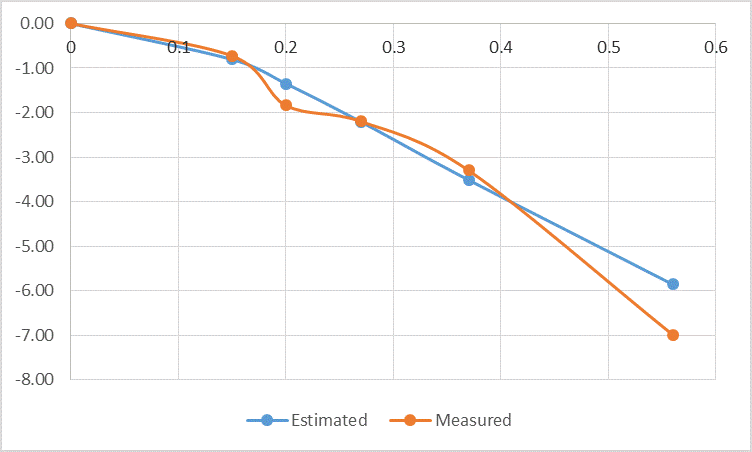
Figure 2 Comparison of measured and estimated lead heat attenuation in decibels (dB) versus length of distal segment (in meters).