2632
Characterization of gradient-induced vibration: Can optical displacement sensors be replaced by miniature accelerometers?1MR:comp GmbH, Gelsenkirchen, Germany, 2MRI-STaR GmbH, Gelsenkirchen
Synopsis
In this study the suitability of a miniature accelerometer for vibration measurements according to ISO/TS 10974 was investigated. Gradient-induced vibration of a titanium disc was measured both with an electric accelerometer and an optical displacement sensor and the obtained datasets were compared. Taking the characteristics of the setup into account, the results indicate that the used type of accelerometer is suitable to meet the specifications given in ISO/TS 10974.
Introduction
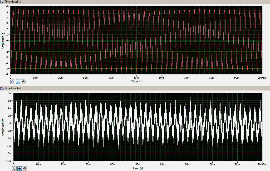
Vibratory forces caused by the interaction of the gradient-induced eddy current magnetic moments of an active implantable medical device (AIMD) with the static magnetic field (B0) are a well-known safety hazard in MR imaging. Following the specifications given in ISO/TS 10974 Clause 10, the use of vibrometers or other optical measurement systems is recommended [1] which requires a complex setup and calibration in order to generate reliable measurement results. In this investigation a comparative vibration measurement of a titanium disc as a dummy device under test (DUT) was conducted to assess the suitability of an adhesive miniature accelerometer for measuring gradient-induced vibration. This approach has the advantage of a significantly lower noise level (see FIG. 1) and secondly excludes artefacts caused by an insufficient alignment. The measurement on the other hand could be influenced by the extra weight of the sensor and its fixation. The goal of this study was to investigate under what circumstances an electric accelerometer can replace an optical measurement setup given the specifications in ISO/TS 10974. An optical displacement sensor was used to generate reference values.Method
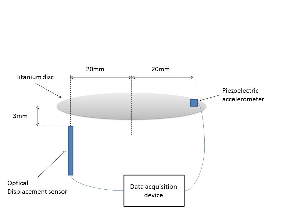
Measurements were conducted in a clinical 1.5T Avanto and a 3T Verio MR scanner (Siemens Healthineers, Germany).The DUT (Titanium disc, diameter = 46.7 mm; weight = 4.14 g) was suspended by strings (aligned parallel to the X-axis) and placed in coronal orientation inside the MR bore at a location with the highest achievable gradient field in Y-direction. The setup was fixed onto the patient table decoupled from the vibrations of the MR scanner. The accelerometer “MRacc” (MRI-Tec, Germany, height = 3.5 mm; diameter = 2.2 mm; weight = 0.18 g) was fixed on top of the main surface of the titanium disc while the optical displacement sensor “MRI-VRS 100” (MRI-Tec, Germany) was placed approximately 3 mm below the DUT’s surface (FIG. 2). EPI sequences were applied and both the displacement and the acceleration were measured. The gradient field exposure level was measured simultaneously using a 3-planes search coil according to IEC 60601-2-33 [2]. Data was recorded using a data card and software (National Instruments, USA) with a sampling rate of 100 kSa/s. Additional measurements without the DUT were conducted to investigate induced vibration into the accelerometer and the whole test setup. The measured acceleration signal was numerically double-integrated and compared to the data obtained from the displacement sensor. Both datasets were spectrally analyzed with FFT and the resulting frequency spectra were again compared.Results and Discussion
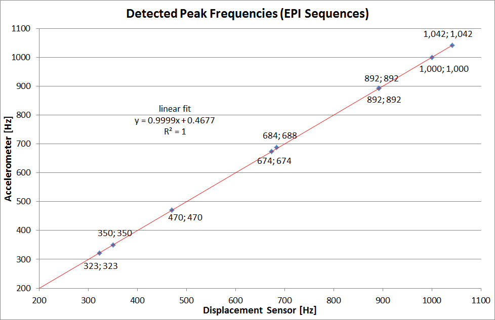
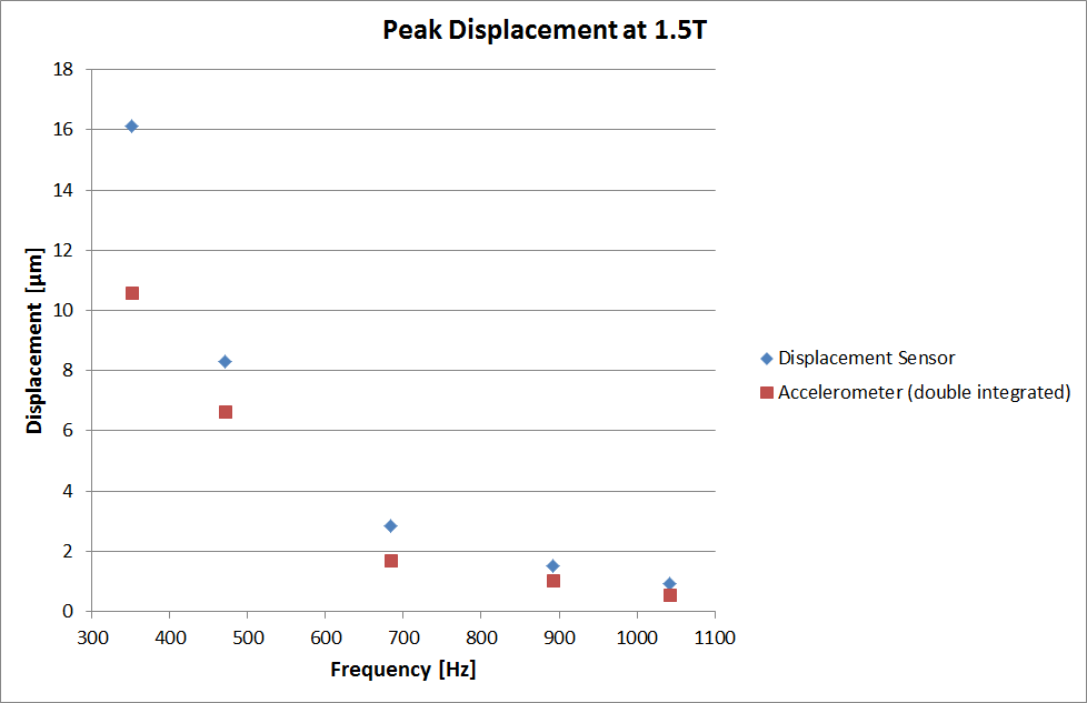
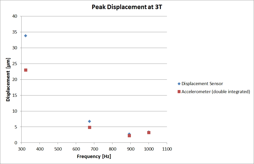
The mean deviation of the detected peak frequencies between the displacement sensor and the accelerometer was 0.06% with a maximum deviation of 0.5% at 685 Hz. Detected peak frequencies of both sensors are plotted versus each other in FIG. 3. A very high correlation between the measurements can be seen (r²=1). Mean discrepancy between measured displacement amplitude and the double-integrated acceleration was 27.7% with a maximum deviation of 39.4%. For all sequences the optical sensor provided higher amplitudes compared to the integrated results of the accelerometer (see FIG. 4 and FIG. 5).This was expected due to the optical sensor being positioned at the opposite side of the DUT as the accelerometer (see FIG. 2). The additional weight of the accelerometer and its fixture causes a shift of the rotational axis away from the center line of the disc towards the accelerometer thus resulting in a higher deflection detected by the optical sensor. Vibration of the test setup was determined at 350 Hz (the largest deflection was measured at this frequency with the 1.5 T Avanto) with a detected displacement of 87 nm which was 0.82% of the DUT’s deflection at the same sequence. Therefore the vibration of the setup was considered negligible.Conclusion
This investigation shows that the presented miniature accelerometer is suitable for measurements in accordance with the specifications given in ISO/TS 10974. This can be concluded by the excellent frequency response of the sensor. The small dimensions of the sensor compared to generic vibrometer setups additionally enable the accessibility of higher gradients inside the MRI bore. For precise measurements however careful considerations of the influence of the sensor and its fixture on the mass moment of inertia of the DUT are necessary. The approach to measure vibration with an electronic accelerometer instead of an optical sensor should therefore be included in the recommendations given in ISO/TS 10974 Clause 10.6.3.1.Acknowledgements
No acknowledgement found.References
[1] Technical specification ISO/TS 10974 “Assessment of the safety of magnetic resonance imaging for patients with an active implantable medical device”, 2nd Edition, Blender Version 3.
[2] Technical specification IEC 60601-2-33 IEC. 2010. Ed.3.1. Medical Electrical Equipment - Part 2-33: "Particular requirements for the basic safety and essential performance of magnetic resonance equipment for medical diagnosis."
Figures