2629
Test field diversification method for the safety assessment of RF-induced heating of AIMDs during 1.5-T MRI1IT'IS Foundation, Zurich, Switzerland, 2Department of Information Technology and Electrical Engineering, ETH-Zurich, Zurich, Switzerland
Synopsis
Elongated AIMD can pick up the RF-energy during MR exposure, and locally deposit the energy in the tissue near its vicinity --- typically near the conductive electrodes. Current experimental assessment strategy is capable to achieve only a limited set of AIMD exposure conditions. In this work, we outline a method by which the exposure conditions may be diversified during experimental testing. The feasibility of the method is evaluated for three generic implants. The RF-induced deposited power of the AIMD over more than 1000 exposure conditions was evaluated and approximately 20 dB dynamic range in the deposited power was achieved.
Purpose
The local radiofrequency (RF)-induced heating is one of the most dangerous hazards for patients with active implantable medical devices (AIMDs) undergoing an MRI scan. The power deposited in tissue near an electrode of an elongated AIMD can be substantial and is strongly dependent on the incident field characteristics (magnitude and phase of the electric (E) field, tangential to the conductive wire, Etan)1. While the amount of RF-induced heating is directly proportional to the incident Etan magnitude, diversity of the field polarization can also produce different phase distributions of Etan along the conductive wire; the dependency of the RF-induced heating on the phase of Etan is not trivial. In current assessment strategy outlined in 2,3, only a limited set of implant exposure conditions can be achieved, by means of changing the lead positions inside the exposure field. In this work, we outline an alternative testing method that can be used to increase the number of exposure conditions to the AIMD under test.Method
To determine the feasibility of the proposed method over a wide range of lead lengths, three generic implants (40, 60, and 80 cm insulated wires), similar to that in 4, were characterized with the piece-wise excitation (πX) method at 64 MHz in homogeneous tissue-simulating medium (TSM: εr = 78, σ = 0.47 S/m). The power deposition was estimated for each exposure condition using:
$$P_{tip}= W_{0}(\sum_l h(l)\cdot E_{tan}(l)\cdot dl)(\sum_l h(l)\cdot E_{tan}(l)\cdot dl)^{\star}$$
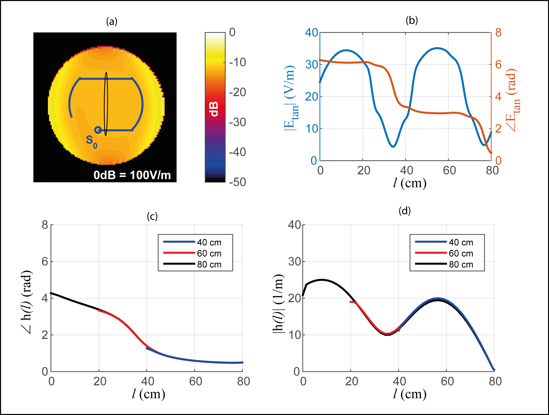
where $$$h(l)$$$ is the model of the implant obtained with method of 4, hereafter referred to as πX model. $$$E_{tan}(l)$$$ is the tangential component of the complex incident E-field along the implant pathway, $$$l$$$, with $$$l = 0 $$$ cm refers to $$$S_{0}$$$ indicated in Figure 1a). $$$W_{0}$$$ is the power deposition for $$$E_{tan} = 1$$$ V/m, and is equal to 608, 231, and 32 µW for the 40, 60, and 80 cm implant, respectively. The implant is placed along a pathway that best accommodates the trade-off between the size of test phantom and the coupling between different segments of the conductive wire and the reflection from finite phantom boundaries, as illustrated in Figure 1a).
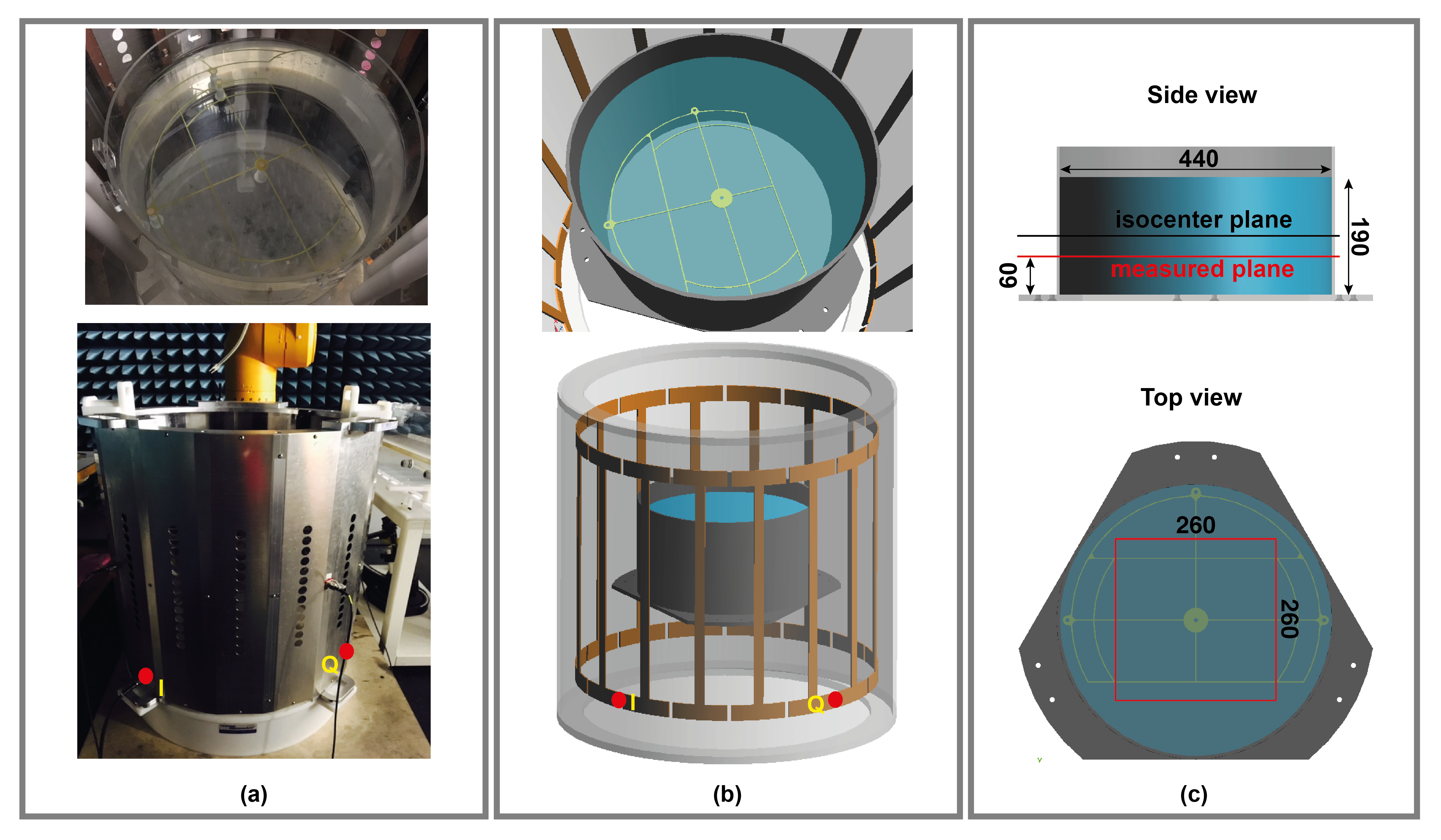
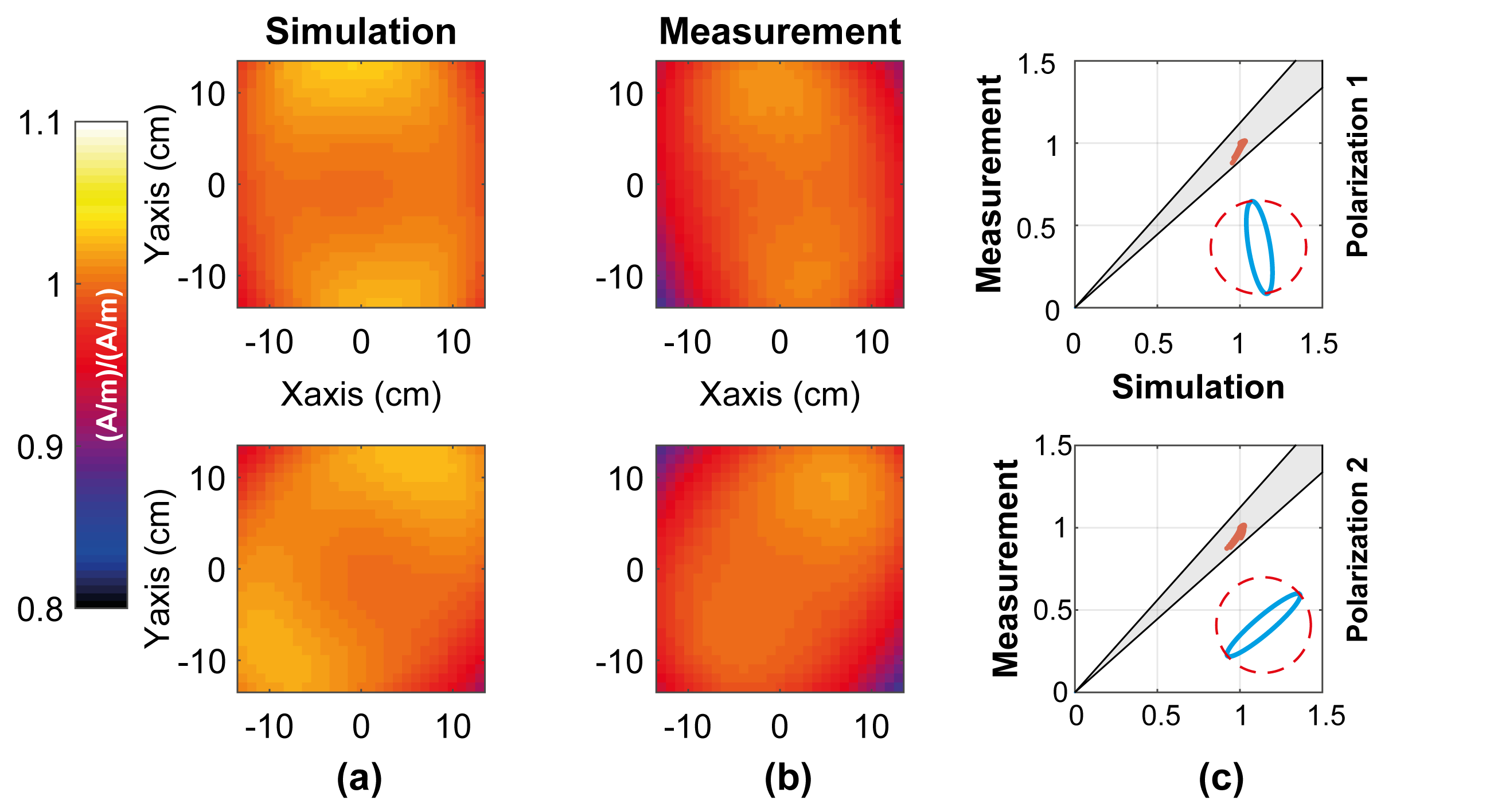
The proposed test setup comprises a cylindrical phantom and a two-feed RF coil as illustrated in Figure 2. By adjusting the relative magnitude and phase between the feeds (I and Q), diverse exposure conditions can be achieved. The exposure condition was characterized with respect to the polarization of the B1-field at the center of the phantom. The spatial distribution of the total B1-field over an area (see Figure 2c)) were validated against experimental results for 2 exposure conditions. The experimental and numerical uncertainty are assessed to be 0.8 and 0.5 dB, respectively. Thus the combined total uncertainty (k=1) is 1.0 dB.
Results
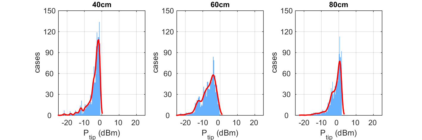
Figure 1a) shows the spatial distribution of the total E-field in the axial plane of the implant and the polarization of the incident B1-field for a selected exposure condition. The corresponding $$$E_{tan}$$$ along the implant pathway of figure 1a) is illustrated in figure 1b). The πX models of the three generic implants are illustrated in figures 1c) and 1d). Figure 3 shows the measured and simulated spatial distributions of the total B1-field of two selected exposures. The deviation between experimental and numerical evaluations of the total B1-field was found to be less than 1 dB, which is within the combined uncertainty. Figure 4 shows histograms of predicted power deposition for the generic implants inside the test phantom for incident field conditions generated from 1480 B1-polarizations. For all implants and exposure conditions, we found a dynamic range for the RF-induced power deposition of around 20 dB.Conclusions
We present the feasibility study of a test field diversification method that can be used for extensive assessment of RF-induced power deposition of AIMDs. Our numerical feasibility study reports a dynamic range of approximately 20 dB in the induced power deposition achieved for lead lengths from 40 – 80 cm. We expect a lesser achievable performance when accounts for the non-ideality in experimental evaluation. Further investigation on the experimental implementation of the method and extension to 128 MHz (3T-MRI) is required. We envision that a set of exposure conditions can be chosen wisely in practice to obtain diverse high-fidelity testing conditions for RF-induced heating assessment of AIMDs. Once proven practical, the proposed method is compliant with the radiated immunity tests required in ASTM 2182 2 and ISO/TS 10974 3 and may improve the safety assessment of medical implants.Acknowledgements
No acknowledgement found.References
1. C. J. Yeung, R. C. Susil, and E. Atalar. RF heating due to conductive wires during MRI depends on the phase distribution of the transmit field. Magn. Reson. Med., 2002; 48:1096–1098.
2. ASTM F2182-11, Standard test method for measurement of radio frequency induced heating near passive implants during magnetic resonance imaging. ASTM International 2011.
3. ISO/TS. 10974:2016, Requirements for the safety of magnetic resonance imaging for patients with an active implantable medical device. ISO/TS 10974 2016.
4. E. Zastrow, M. Capstick, E. Cabot, and N. Kuster, “Piece-wise Excitation System for the Characterization of Local RF-Induced Heating of AIMD during MR Exposure,” EMC'14, Tokyo, 2014; 241–244.
Figures