2628
Test medium derivation for the safety assessment of RF-induced heating of leaded cardio implants during 1.5-T MRI1IT'IS Foundation, Zurich, Switzerland, 2Department of Information Technology and Electrical Engineering, ETH-Zurich, Zurich, Switzerland
Synopsis
It is a common practice that an equivalent mathematical model of an implant is used to estimate in vivo power deposition caused by RF-implant interactions. The model is often derived under in vitro conditions. We assess the suitability of test media for RF-induced heating model derivation at 64 MHz. Based on simple generic leaded-implants, our preliminary analysis shows that the test medium specified in ASTM 2182 (εr = 78, σ = 0.47 S/m) may be appropriate for the safety assessment of leaded cardio implants with respect to RF-induced heating. Future analysis shall include implants with diverse topology and increased realism.
Purpose
The piece-wise excitation method is one of the accepted methods for modeling RF-heating of leaded implants1. At present, an equivalent model of an implant is derived from recommended in vitro conditions. Such conditions include the use of appropriate test fields conditions and tissue-simulating medium (TSM) properties. Because the power deposition caused by implant-RF interactions during MRI is a function of the physical properties of the implant and the surrounding media, it is logical that the modeling be derived under test medium that closely approximates the dielectric properties of the immediate surrounding tissue. Blood (εr = 86, σ = 1.2 S/m) is considered as the predominant tissue for leaded cardio implants and it is recommended by ISO/TS 10974 2 that the TSM with dielectric properties resembling blood is used in the modeling of leaded cardio implants. The electrical conductivity of the TSM proposed in ASTM F21823 (εr = 78, σ = 0.47 S/m, referred to as HPM0.47) is based on the tissue-averaged conductivity whereas for TSM recommended in ISO/TS 109742 (εr = 78, σ = 1.2 S/m, referred to as HPM1.2) is based on the conductivity of blood; the permittivity of both TSMs is based on that of water. Here, we assess the suitability of these two TSMs, which are commonly used in practice, for the safety evaluation of leaded cardio implants. In this study, HPM0.47 and HPM1.2 are used in the Tier 3 evaluation of generic leaded cardio implant. The Tier 3 prediction of in vivo power deposition of 18 clinical variants is obtained and each is compared to its corresponding full-wave Tier 4 estimate.Method
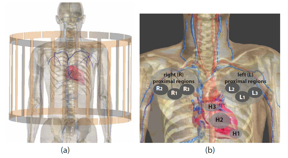
Generic leaded implants of different lengths (380 mm and 340 mm) with 1.0-mm-diameter conductor and 0.5-mm-thick insulation layer with the insulation at the distal termination removed over length of 2-mm are considered in this work. Figure 1 illustrates the exposure condition and the 18 implant routings considered for the Tiers 3 and 4 evaluations. The virtual patient, Duke4, is positioned within the RF birdcage coil as shown in figure 1(a) to mimic a thorax imaging condition. The 18 implant routings are illustrated in figure 1(b); three distal termination sites inside the heart --- H1, H2, and H3 --- are considered. For each distal termination, we define six unique proximal terminations on both right and left side of the chest --- R1, R2, R3, L1, L2, and L3.
In Tier 3 evaluation2, the in vivo power deposition is estimated from:
$$P_{tip}= W_{0}(\sum_l h(l)\cdot E_{tan}(l)\cdot dl)(\sum_l h(l)\cdot E_{tan}(l)\cdot dl)^{\star}$$
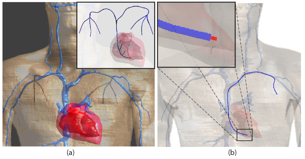
where $$$h(l)$$$ is the Tier 3 model of the lead characterized with the piece-wise excitation method (πX)1,5 at 64MHz. $$$E_{tan}(l)$$$ is the tangential component of the complex incident E-field along an implant routing. $$$W_{0}$$$ is the power deposited at the vicinity of the electrode in each TSM when the implant is exposed to an incident electric field with constant amplitude and phase ($$$E_{tan}= 1 V/m$$$). For Tier 3 evaluation, $$$P_{tip}$$$ is calculated for the 18 implant routings, with $$$h(l)$$$ derived in both homogeneous HPM0.47 and HPM1.2. For Tier 4 evaluation, a generic leaded cardio implant is integrated into the virtual patient, Duke, along each clinical routing predefined in Tier 3 evaluation (see figure 2). The 380-mm and 340-mm implants are integrated along the left- and right-proximal routings, respectively. A full-wave FDTD simulation is performed for each implant.
Results and Conclusions
Figure 3 summarizes the Tier 3 power deposition for each implant, estimated with HPM0.47- and HPM1.2-derived πX models, and the corresponding Tier 4 estimates. The value obtained from HPM0.47-derived πX model shows an average deviation of 0.75 dB and a maximum deviation of 1.7 dB from the Tier 4 results, while the average and maximum deviations from Tier 4 results are 1.7 and 3.5 dB for HPM1.2-derived πX model. This preliminary results show that HPM0.47 is no less suitable than HPM1.2 for the safety assessment of leaded cardio implants with respect to in vivo RF-induced heating. A variety of conductor topology (helical/coiled or straight/cable) and insulation thickness must be considered in future work to determine the optimal test medium for cardio implants, as well as for other types of implants. Furthermore, we hypothesize that there exists an appropriate medium for each type of implants (cardiac pacemakers, spinal cord stimulator, and etc.) and rigorous derivation method of the optimal medium shall be proposed in future work. Lastly, experimental practicality favors TSMs that can be repeatedly and easily produced and the usability of the proposed TSMs must be considered in any future work.Acknowledgements
No acknowledgement found.References
1. Park SM, Kamondetdacha R, Nyenhuis JA. Calculation of MRI-induced heating of an implanted medical lead wire with an electric field transfer function. J MagRes Imag 2007; 26:1278 –1285.
2. ISO/TS. 10974:2016, Requirements for the safety of magnetic resonance imaging for patients with an active implantable medical device. ISO/TS 10974 2016.
3. ASTM F2182-11, Standard test method for measurement of radio frequency induced heating near passive implants during magnetic resonance imaging. ASTM International 2011.
4. Gosselin M C, Neufeld E, Moser H, Huber E, Farcito S, Gerber L, Jedensjo M, Hilber I, Gennaro F D,Lloyd B, Cherubini E, Szczerba D, Kainz W & Kuster N. Development of a new generation of high-resolution anatomical models for medical device evaluation: The Virtual Population 3.0. Physics in Medicine and Biology 2014; 59: 5287 – 5303.
5. Zastrow E, Capstick M & Kuster N. Experimental system for RF-Heating characterization of medical implants during MRI. In `Proceedings of the 24th Annual Meeting of ISMRM' 2015: 0912.
Figures