2626
Quantification and impact of lead coupling on RF-induced heating in MRI.1Université de Lorraine, IADI, Nancy, France, 2INSERM, U947, Nancy, France, 3Healtis, Nancy, France, 4CHRU Nancy, France, 5INSERM, CIT-1433, Nancy, France
Synopsis
Patients carrying multiple leads like abandoned pacemaker leads are still denied MRI scans, as their situation is not currently covered by the existing safety guidelines. Therefore, to assess the impact of lead coupling regarding radiofrequency-induced heating, temperature measurements were performed on different types of simplified leads and coupling factors were introduced to quantify and evaluate the phenomenon. The lead coupling can have a significant impact on temperature and can either induce higher or lower temperatures compared to the case when the leads are alone, and thus should be considered in future MRI safety standards.
Purpose
Radiofrequency (RF) safety in MRI for medical devices like pacemakers1 is of great importance as the worldwide population is aging and requiring more MRI scans2. There is a need to assess the safety of patients carrying multiple leads3-4, as it is not yet covered by the existing MRI compatibility standards5. Thus, the purpose of this study is to experimentally observe the lead coupling regarding RF-induced heating with different simplified leads, to have a better insight on the phenomenon occurring and thus approach safety guidelines suitable for every patient carrying multiple leads.Methods
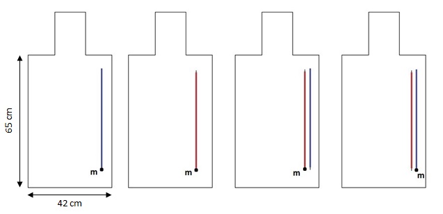
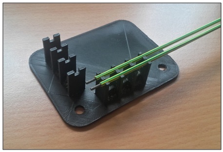
Two 40-cm long simplified leads were made of straight hardened steel wires of 1.5 mm diameter with a 0.375 mm-thick polyolefin insulation (heat-shrink tube). As these hardened steel wires which were easily available and perfectly straight were also magnetic, two other leads were made the exact same way except with non-magnetic and non-perfectly straight stainless steel wires, to check if this property affected the RF-induced heating and coupling. To verify the occurrence of a coupling phenomenon in different lead models, two other leads of the same length were made using a coaxial cable with its metallic shield removed; the stainless steel wire diameter was 0.92 mm and the PTFE insulation thickness was 1 mm. All leads were left bare along 5 mm at their extremity to represent the electrodes. In each set of leads, one lead was also left bare at the other extremity over a length of 2 mm, called the “uncapped” lead and the other, insulated, was the “capped” one, to have different termination conditions. Different configurations were studied for each set of leads (Figure 1), embedded at the right side of an ASTM gel phantom6 and supported by a dedicated 3D-printed plastic support and smaller 3D-printed plastic guides along the leads (Figure 2). When both leads were together, they were spaced 2.5 mm. The experiments were conducted so that there was no lead or temperature probe displacement during the measurements on the same lead (alone or in presence of the other lead). A fiber optic temperature probe (NEOPTIX T1, Neoptix, Quebec City, Canada) was positioned orthogonally on the same 3D-printed support to ensure the accuracy of measurements at the extremity of the leads. A 3’24 duration FSE-XL ASTM6 RF-heating sequence was then performed on the phantom inside a 1.5 T GE Signa HDx MRI scanner (General Electric Healthcare, Milwaukee, WI, USA) and the temperature was acquired in real time with the temperature probe software. The experiments were repeated, some of them several months apart, to assess the repeatability of the observations. The first leads are referred to as leads #1, the non-magnetic ones used to check the influence of this property as leads #2, and the leads made from coaxial cables as leads #3. A coupling factor CF was calculated for each lead as the ratio between the temperature elevation of the leads when they are both present and when they are alone.Results
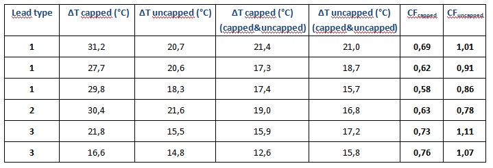
The temperature elevations and coupling factors are reported in Table 1. The
mean value for CFcapped in the #1 leads set is 0.63±0.05 (CI95%),
and the mean value for CFuncapped in the same leads set is 0.93±0.07
(CI95%). Depending on the experiment, CFuncapped values can
be higher or less than 1. Discussion
The difference in absolute temperature elevations between two measurements for the same leads can mainly arise from the position of the temperature probe at the extremity of the leads in the gel phantom. However, the experimental setup ensured a proper repeatability of the coupling factors values. The magnetic property of leads #2 does not seem to have an influence on the temperature elevations, thus leads #1 experiments are relevant to study lead coupling regarding radiofrequency. The coupling factors values on these simplified leads suggest that coupling can have a significant impact on temperature elevation, up to 40%. Moreover, the different CFuncapped values show that lead coupling can either induce higher or lower temperatures: this highlights the complexity of this phenomenon and indicates that the presence of another lead can have an effect on RF-induced heating, and therefore should be studied carefully.Conclusion
This study highlights the complex nature of lead coupling in MRI, and shows that the observations about lead coupling inducing higher or lower temperatures could be essential for MRI compatibility safety standards of medical devices when considering several leads. Experiments on real medical devices leads (for example pacemakers’) will be performed to verify the impact of lead coupling in more realistic leads.Acknowledgements
The authors thank the Région Lorraine and FEDER for financial support.References
1. Boilson BA, Wokhlu A, Acker NG, Felmlee JP, Watson RE, Julsrud PR, et al. Safety of magnetic resonance imaging in patients with permanent pacemakers: a collaborative clinical approach. Journal of Interventional Cardiac Electrophysiology. 2012 Jan;33(1):59–67.
2. Philips, data on file. Based on Millennium research group reports RPUS21LJ15; RPUS20SP15; RPGL12CR14.
3. Higgins JV, Gard JJ, Sheldon SH, Espinosa RE, Wood CP, Felmlee JP, Cha YM, Asirvatham SJ, Dalzell C, Acker N, Watson RE, Friedman PA. Safety and Outcomes of Magnetic Resonance Imaging in Patients with Abandoned Pacemaker and Defibrillator Leads. Pacing and Clinical Electrophysiology, 2014;37: 1284–1290.
4. Mattei E, Gentili G, Censi F, Triventi M, Calcagnini G. Impact of capped and uncapped abandoned leads on the heating of an MR-conditional pacemaker implant: MR-Conditional Pacemaker Implant and Abandoned Lead. Magn Reson Med. 2015 Jan;73(1):390–400.
5. ISO/TS 10974:2012, Assessment of the safety of magnetic resonance imaging for patients with an active implantable medical device.
6. ASTM F2182-11a, Standard Test Method for Measurement of Radio Frequency Induced Heating On and Near Passive Implants During Magnetic Resonance Imaging, 2011.
Figures