2620
Gradient Heating of Bulk Metallic Implants1Physikalisch-Technische Bundesanstalt (PTB), Braunschweig und Berlin, Germany
Synopsis
The temperature increase of an excised hip prosthesis was measured under exposure to the switched gradients of a clinical 3T scanner. For the acetabular cup, insulated or embedded in gelatin gel, temperature increases of ΔT=25.8 K and 3.8 K, respectively, were observed within 10 min. From the initial temperature increase of up to 110 mK/s a gradient-induced heating power of PG = 370 W/kg in adjacent muscle can be derived and this quantity's relation to local SAR is discussed. The results suggest that gradient-induced heating of bulk metallic implants cannot automatically be assumed to be negligible.
INTRODUCTION
The possibility of hazardous tissue heating near metallic implants is well established1-3 for the RF case but studies looking at gradient-switching effects are scarce.4 Recently, a numerical simulation study of gradient induced heating of a hip prosthesis showed a temperature increase of up to 20 K in the implant and the surrounding tissue.5 This seemed to contradict Ref. (4) where no measurable effects were found in a realistic prosthesis. The present work aims to measure the gradient-induced power absorption and heating of a common hip prosthesis on a clinical scanner.METHODS
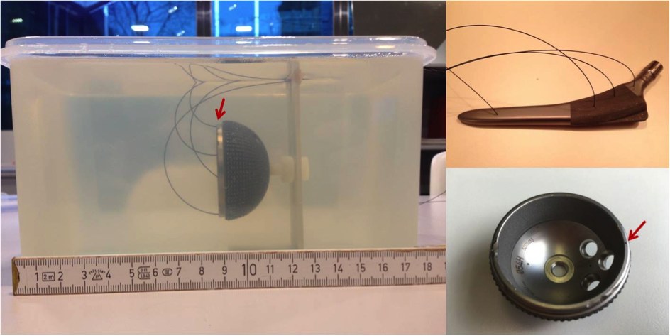
Cup (Aesculap Plasmafit Plus3, 54 mm diameter) and stem (Aesculap Excia, 180 mm) of an excised hip prosthesis, both made from Ti-6Al-4V alloy, were investigated separately, both either insulated in polystyrene or embedded in gelatin gel (Fig. 1). Temperature was monitored by fiber-optical sensors. The implants were placed at positions P1 $$$(x=-15\,\mathrm{cm}, y=-9\,\mathrm{cm}, z=-30\,\mathrm{cm})$$$ or P2 $$$(x=-20\,\mathrm{cm}, y=0\,\mathrm{cm}, z=0\,\mathrm{cm})$$$ in a clinical 3T scanner (Siemens Verio). P1 was chosen according to manufacturer gradient maps for maximum $$$|dB/dt|$$$ in a realistic patient position, P2 corresponds to Ref. (4). The stem was oriented in the natural direction whereas the cup's symmetry axis was parallel to the z-direction.
For maximum effect a self-written EPI-like sequence with continuous trapezoidal gradients $$$(G_{max}=20\,\mathrm{mT/m},\,f=2.0\,\mathrm{kHz},\,S=200\,\mathrm{Tm^{-1}s^{-1}})$$$ was applied; the product EPI and bSSFP sequences were used for comparison. Experiments were performed in normal operating mode with all safety features in place; patient scanning would have been permissible. RF was off.
RESULTS
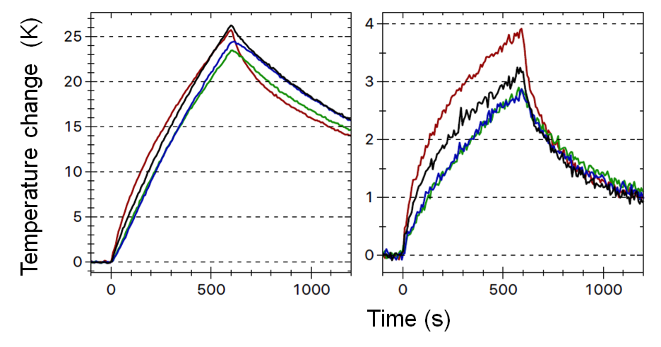
Fig. 2 shows the temperature change of the cup under trapezoidal z-gradients. Increases of ΔT=25.8 K and 3.8 K within 10 min were observed for the insulated and embedded cup, respectively, at P1. After 40 min ΔT was 6.0 K for the embedded implant and not yet saturated. If the adjacent tissue follows the implant temperature, as it was found in Ref. (5), a gradient-induced specific heating power $$$P_G$$$ can be derived via $$$P_G=k_0\,c_T$$$, where $$$k_0\equiv dT /dt\mid _{t=0}$$$ is the initial slope of the temperature curve and $$$c_T$$$ the tissue's specific heat capacity. For the insulated implant $$$k_0=110\,\mathrm{mK/s}$$$ is determined; the value for the embedded implant is consistent within (much larger) errors. For, e.g. muscle with6 $$$c_T=3400\,\mathrm{Jkg^{-1}K^{-1}}$$$ this results in $$$P_G=370\,\mathrm{W/kg}$$$. Heating rates for product sequences were lower but could still be substantial: $$$k_0=40\,\mathrm{mK/s}$$$ (EPI, P1), $$$k_0=6.8\,\mathrm{mK/s}$$$ (bSSFP, P1), $$$k_0=2.6\,\mathrm{mK/s}$$$ (bSSFP, P2). Heat generation in the prosthesis stem was about an order of magnitude lower, which was partially offset by lower heat losses. At the implant position the self-written sequence generated an average $$$|dB/dt|_{rms}=49.7\,\mathrm{T/s}$$$, i.e. less than the FPO:B limit1 of $$$56\,\mathrm{T/s}$$$ for implant scanning.DISCUSSION
Gelatin gel approximates water-like tissue with respect to thermal conductivity but heat dissipation by perfusion is missing. Despite this severe limitation temperature increases of 6 K at the surface of the embedded implant must raise some caution. The gradient-induced heating power $$$P_G$$$ is independent of surrounding tissue and thus can reliably be determined on the insulated prosthesis. A comparison of $$$P_G$$$ and local SAR is tempting but requires caution. Based on an implicit model of heat dissipation in tissue the SAR rationale1 aims to prevent hazardous temperatures by limiting the local heat generation term to 20 W/kg. In this sense $$$P_G$$$ and local SAR are comparable and our measured values exceed the local-SAR limit substantially. $$$P_G$$$ applies, on the other hand, only to a possibly very thin layer of tissue adjacent to the implant while spatial averaging over 10 g of tissue is an integral part of the SAR-based safety concept.
That no measurable effect was detected in Ref. (4), where the product bSSFP sequence was used on a prosthesis stem at position P2, is explained by the present results. A quantitative comparison to Ref. (5) was not possible as those sequence parameters are not supported by our gradient system; qualitatively our measurements confirm those findings.
CONCLUSION
From the scarce data presented here it cannot be concluded that gradient heating of bulk metallic implants is automatically dangerous. But the measured temperature increase and heat generation rates should be alarming. Gradient heating of orthopedic prostheses cannot simply be ignored and the effect must be included in any safety assessment. This implies that another safety-critical zone at the end of the gradient coil exists, relatively far away from the iso-center and well outside of the footprint of the RF transmit coil.Acknowledgements
We are grateful to P. Waxmann for programming the gradient sequence, Jochen Rohrbeck, MD, for providing the excised prosthesis and Siemens Healthcare for providing the gradient field maps.References
1. IEC 60601-2-33, Particular requirements for the safety of magnetic resonance equipment for medical diagnosis. Ed. 3.2, IEC, Geneva, Switzerland (2015)
2. ISO/TS 10974 Assessment of the safety of magnetic resonance imaging for patients with an active implantable medical device. ISO, Geneva, Switzerland (2012).
3. Establishing Safety and Compatibility of Passive Implants in the Magnetic Resonance (MR) Environment; Guidance for Industry and Food and Drug Administration Staff. US Food and Drug Administration. Silver Spring, MD, USA (2014).
4. Graf H, Steidle G, Schick F. Heating of metallic implants and instruments induced by gradient switching in a 1.5-Tesla whole-body unit. J Magn Reson Imaging 2007;26:1328-33.
5. Zilberti L, Bottauscio O, Chiampi M, Hand J, Lopez HS, Brühl R, Crozier S. Numerical prediction of temperature elevation induced around metallic hip prostheses by traditional, split, and uniplanar gradient coils. Magn Reson Med. 2015; doi: 10.1002/mrm.25687. [Epub ahead of print].
6. Hasgall PA, Di Gennaro F, Baumgartner C, Neufeld E, Gosselin MC, Payne D, Klingenböck A, Kuster N. IT’IS Database for thermal and electromagnetic parameters of biological tissues. Version 3.0 (2015), doi: 10.13099/VIP21000-03-0. www.itis.ethz.ch/database. Accessed Nov 1, 2016.
Figures