2604
Radiofrequency applicator concepts for simultaneous MR imaging and hyperthermia treatment of glioblastoma multiforme: A 7.0 T (298 MHz) study1Berlin Ultrahigh Field Facility (B.U.F.F.), Max Delbrück Center for Molecular Medicine in the Helmholtz Association, Berlin, Germany, 2MRI.TOOLS, Berlin, Germany, 3Clinic for Radiation Oncology, Charité Universitätsmedizin, Berlin, Germany, 4Experimental and Clinical Research Center (ECRC), a joint cooperation between the Charité Medical Faculty and the Max Delbrück Center for Molecular Medicine in the Helmholtz Association, Berlin, Germany
Synopsis
Glioblastoma multiforme is the most frequent and most aggressive malignant braintumor with de facto no long term curation by the use of current multimodal therapeutic approaches. RF heating at ultrahigh fields (B0=7.0T, f=298MHz) has the potential of delivering sufficiently large thermal dosage for hyperthermia of relatively large tumor areas. This work focuses on EMF simulations and provides realistic applicator designs tailored for simultaneous RF heating and MR imaging. Our preliminary results suggest that RF power can be focused to both a small tumor area and a big clinical target volume based on segmented patient data.
Purpose
Glioblastoma multiforme is the most frequent and aggressive malignant braintumor with no long term curation by the use of current multimodal therapeutic approaches1. A prospective randomized trial showed the principal effectiveness of brachytherapy and enhancing interstitial hyperthermia, prolonging median survival2. The invasiveness of this approach is a major road blocker for wider clinical application, thus the need for non-invasive thermal therapy solutions is obvious. Simultaneous RF-heating and MR imaging at ultrahigh fields (B0=7.0T, f=298MHz)3-7 has the potential of delivering sufficiently large thermal dosage for hyperthermia of relatively large tumor areas. En route to a potential RF-induced hyperthermia treatment of glioblastoma in the human brain, this work focuses on electromagnetic field (EMF) simulations and provides realistic applicator designs tailored for simultaneous RF-heating and MRI.Methods
EMF simulations8 were performed for two voxel models of the human head:
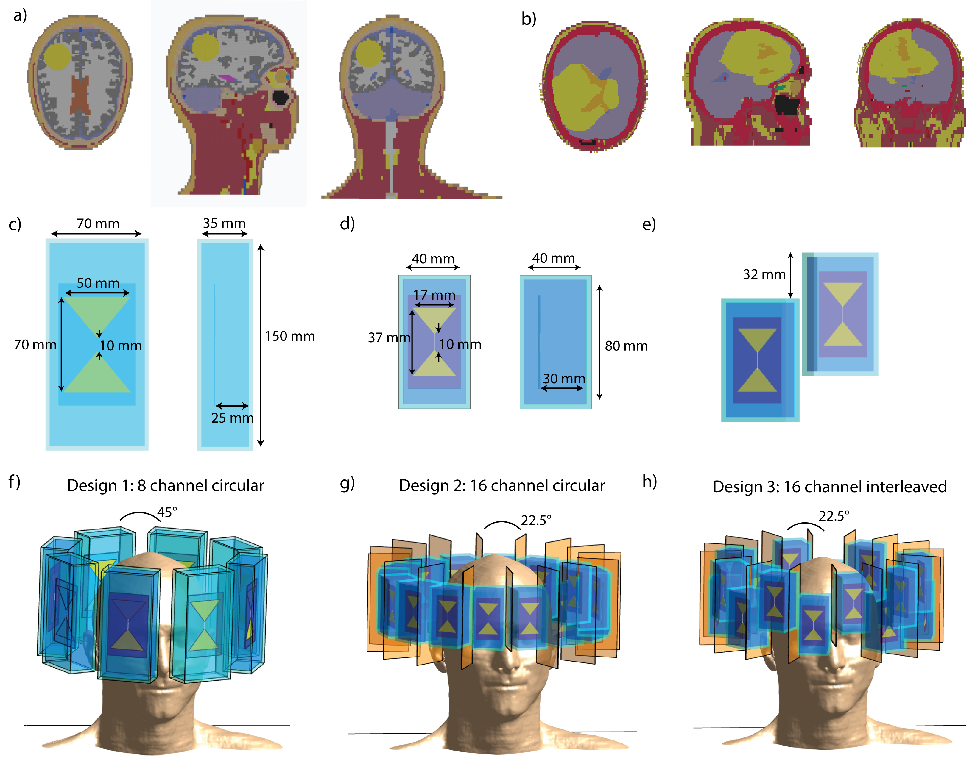
1) Voxel model “Duke”9 was upgraded with a sphere (d=4cm, σTumor=1.15S/m, εTumor=66.510) in the right occipital region of the brain, mimicking a glioblastoma (Fig.1a).
2) A real clinical computed tomography dataset of a patient with glioblastoma multiforme was segmented into 18 contours and assigned EM material properties of tissue11(Fig.1b).
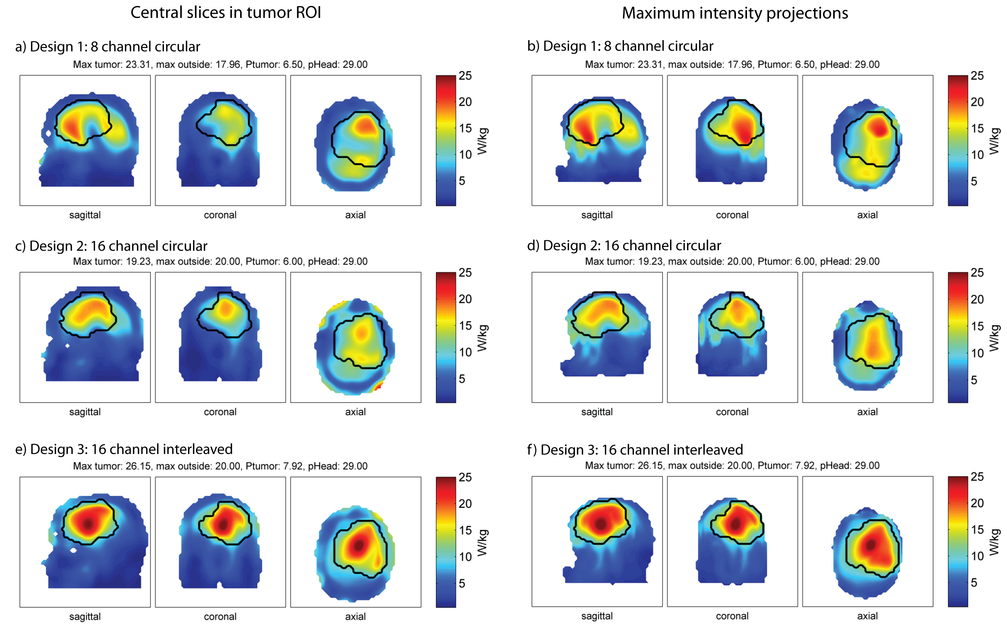
Three RF antenna arrays were modeled, each comprising bowtie electric dipole antennae in a circular arrangement. These building blocks demonstrated good RF heating and MR imaging performance at f=298MHz3,12. The first configuration consists of eight antennas ((35x70x150)mm³ each) positioned symmetrically (diameter=24cm) around the human head (Fig.1c,f) with D20 (ε≈80) as high permittivity medium for wavelength shortening and antenna size reduction13. The second configuration constitutes a 16-channel array ((40x40x80)mm³ each;Fig.1d,g). A higher permittivity dielectric (ε≈200) allowed further antenna size reduction and can be realized by mixing high permittivity BaTiO3 powder with D20. In the third configuration, sixteen antennae ((40x40x80)mm³,ε≈200) were positioned interleaved along the z-direction(Fig.1e,h). Copper sheets were used to decrease next neighbor coupling (Fig.1g,h).
The multi-channel point-SAR distributions were rebinned14 to an isotropic grid of 5mm and averaged15 over 10g16. In the non-tumor region, VOPs17 were calculated for faster optimization. A multiquadratic optimization problem was simplified via its semidefinite relaxation18, which was solved using the MatLab-based modeling system for convex optimization (CVX19) with different constraints. For small tumors, the optimization goal is set to maximize total power absorption in the tumor volume:
maximize Tr(XQ) s.t. Tr(XVi)≤SARmax & Tr(XP)≤Pmax
where X=solution matrix, Q=tumor-SAR matrix, Vi=generalized VOPs. Head power deposition was constrained via the global SAR matrix P.
Large tumors are subject to a maximum homogenized power distribution within the tumor18:
minimize t s.t. -t≤Tr(XQi)-b≤t & Tr(XVi) ≤SARmax & Tr(XP)≤Pmax
with b=targeted tumor-SAR.
Results
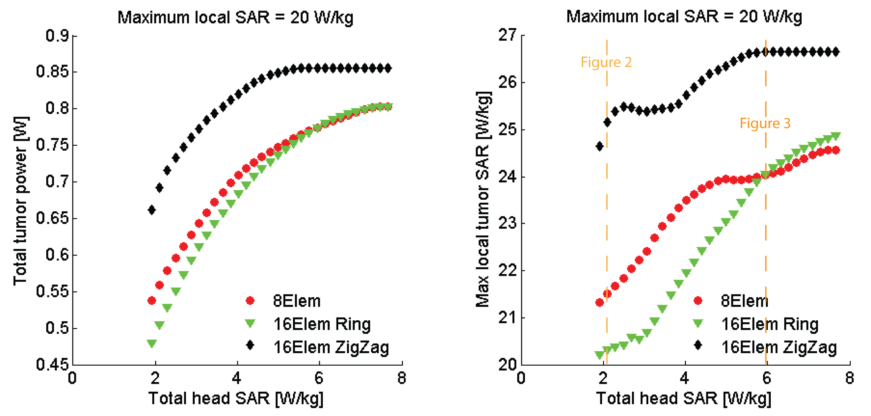
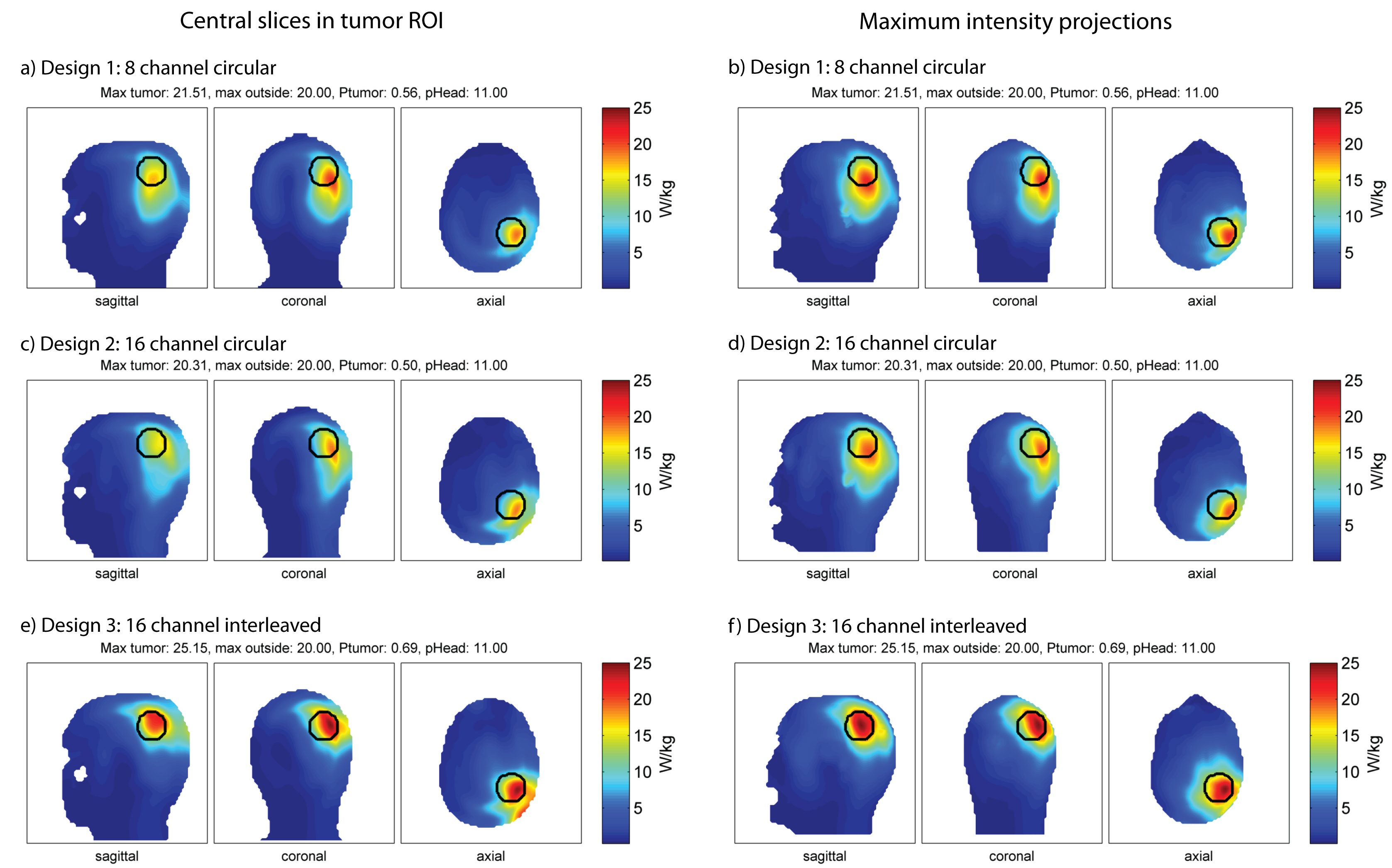
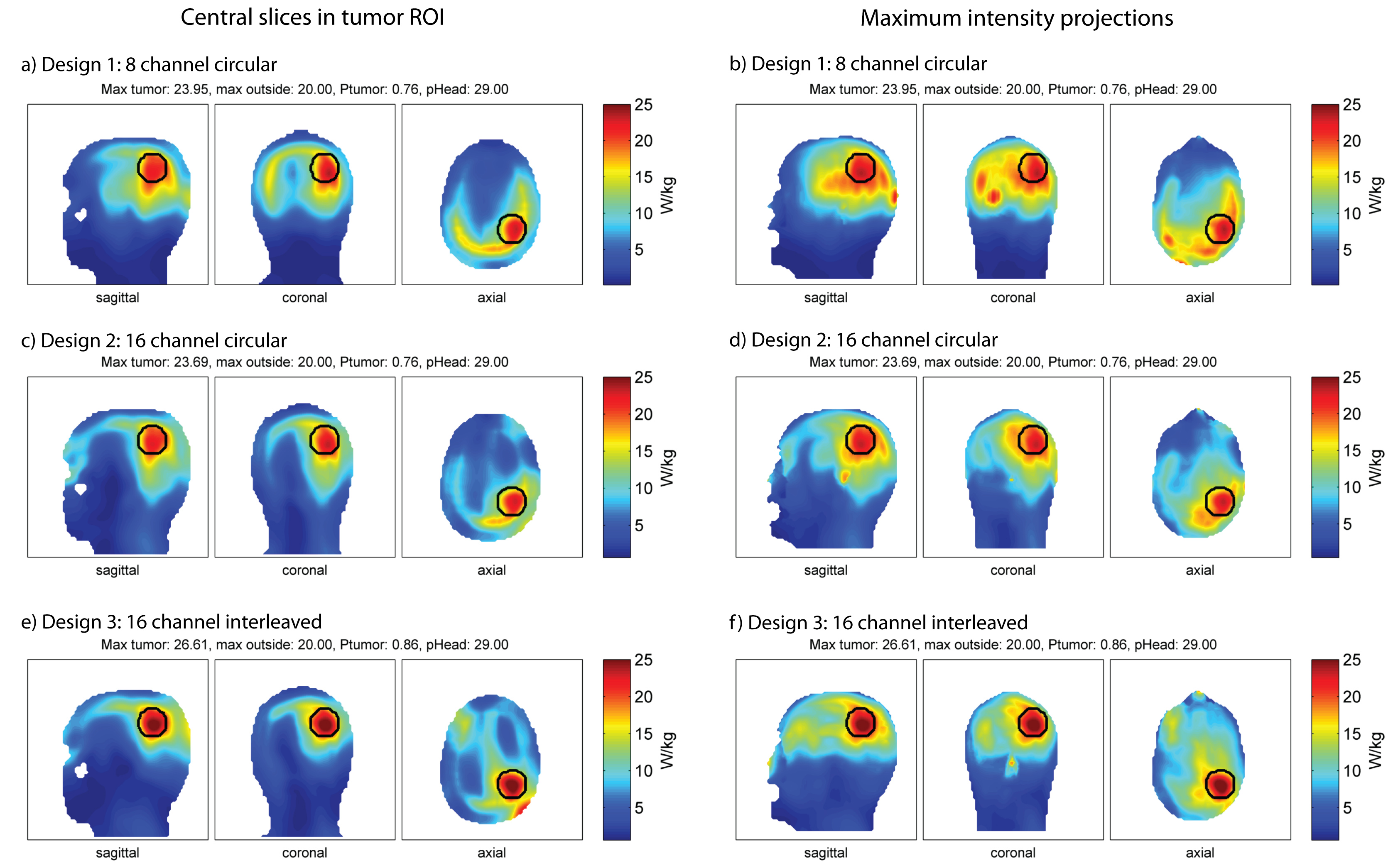
For all configurations, a SAR hotspot could be generated in the target region. For the small tumor in “Duke”, all applicator configurations are evaluated for increasing allowed total head power (Fig.2). The interleaved array is superior in total absorbed tumor power for all optimized total head-SAR constraints. The results for a total head power of 11W/29W are displayed in Fig.3 and 4. Optimized under the constraints of maximum local SAR outside the tumor region SARout ≤20W/kg and total head power PHead≤11W (Fig. 3), the total tumor power was 0.56W for the 8-channel, 0.50W for the 16-channel circular and 0.69W for the 16-channel interleaved antenna array. The maximum local SAR found in the tumor was 21.51W/kg for the 8-channel, 20.31W/kg for the 16-channel and 25.15W/kg for the 16-channel interleaved antenna array. Increasing the total head power constraint to PHead≤29W for the same SARout≤20W/kg, tumor power increased to 0.76W for the 8-channel, 0.76W for the 16-channel and 0.86W for the 16-channel interleaved antenna array (Fig.4). Maximum local SAR in the tumor increased to 23.95W/kg for the 8-channel, 23.69W/kg for the 16-channel and 26.61W/kg for the 16-channel interleaved antenna array.
The clinical glioblastoma patient dataset showed absorbed tumor powers of 6.50W for the 8-channel (Fig.5a,b), 6.00W for the 16-channel circular (Fig.5c,d) and 7.92W for the 16-channel interleaved configuration (Fig.5e,f) under the constraints SARout≤20W/kg, PHead≤29W. The 16-channel interleaved configuration improved absorbed tumor power by >20% vs. the 8-channel and by >30% vs. the 16-channel circular setup. Optimization of the latter was limited by a max SAROut=20W/kg at the surface of the voxel model which can be associated with the VOP overestimation.
Discussion & Conclusion
Our preliminary results suggest that RF power can be focused to both a small tumor area (d=4cm) and a big clinical target volume (d≈10cm) based on segmented patient data. A higher number of transmit channels in an interleaved manner improves hyperthermia performance. In the next step, the simulation setup will be extended to temperature optimizations using temperature matrices20 in order to calculate thermal dose (CEM43°C) distributions21.Acknowledgements
The authors would like to express their gratitude to Bastien Guerin for helpful discussions.
This work was supported in part (L.W., E.O., J.D., A.K., T.N., H.W[OE1] .) by the German Federal Ministry of Education and Research, “KMU-innovativ”: Medizintechnik 13GW0102.
References
1. World Cancer Report 2014. World Health Organization. 2014. pp. Chapter 5.16. ISBN 9283204298.
2. P. K. Sneed, P. R. Stauffer, M. W. McDermott, C. J. Diederich, K. R. Lamborn, M. D. Prados, S. Chang, K. A. Weaver, L. Spry, and M. K. Malec, Survival benefit of hyperthermia in a prospective randomized trial of brachytherapy boost+/-hyperthermia for glioblastoma multiforme, Int J Radiat Oncol Biol Phys, vol. 40, pp. 287-295, 1998.
3. L. Winter, C. Özerdem, W. Hoffmann, D. Santoro, A. Müller, H. Waiczies, R. Seemann, A. Graessl, P. Wust and T. Niendorf, Design and Evaluation of a Hybrid Radiofrequency Applicator for Magnetic Resonance Imaging and RF Induced Hyperthermia: Electromagnetic Field Simulations up to 14.0 Tesla and Proof-of-Concept at 7.0 Tesla. PLoS One, 2013. 8(4): p. e61661.
4. L. Winter, C. Oezerdem, W. Hoffmann, T. van de Lindt, J. Periquito, Y. Ji, P. Ghadjar, V. Budach, P. Wust and T. Niendorf, Thermal magnetic resonance: physics considerations and electromagnetic field simulations up to 23.5 Tesla (1GHz). Radiation Oncology, 2015. 10(1): p. 1.
5. B. Guerin, J.F. Villena, A.G. Polimeridis, E. Adalsteinsson, L. Daniel, J.K. White, B.R. Rosen and L.L. Wald, Ultimate hyperthermia: Computation of the best achievable radio-frequency hyperthermia treatments in non-uniform body models, Proceedings of the 24th ISMRM, 2016
6. Pendse M and Rutt B, An algorithm for maximum-SAR Targeted RF Hyperthermia, Proceeding of 24th ISMRM annual meeting, 2016
7. M.A. Ertürk, S.S. Hegde and P.A. Bottomley, Radiofrequency Ablation, MR Thermometry, and High-Spatial-Resolution MR Parametric Imaging with a Single, Minimally Invasive Device. Radiology, 2016: p. 151447.
8. Sim4Life V2.0, ZurichMedTech, Zurich, Switzerland
9. ITIS foundation, Zurich, Switzerland
10. M.C. Restivo, C.A. van den Berg, A.L. van Lier, D.L. Polders, A.J. Raaijmakers, P.R. Luijten and H. Hoogduin, Local specific absorption rate in brain tumors at 7 tesla. Magnetic Resonance in Medicine, 2016. 75(1): p. 381-389.
11. Christ, W. Kainz, E.G. Hahn, K. Honegger, M. Zefferer, E. Neufeld, W. Rascher, R. Janka, W. Bautz and J. Chen, The Virtual Family—development of surface-based anatomical models of two adults and two children for dosimetric simulations. Physics in medicine and biology, 2009. 55(2): p. N23.
12. C. Oezerdem, L. Winter, A. Graessl, K. Paul, A. Els, O. Weinberger, J. Rieger, A. Kuehne, M. Dieringer and F. Hezel, 16-channel bow tie antenna transceiver array for cardiac MR at 7.0 tesla. Magnetic Resonance in Medicine, 2016. 75(6): p. 2553.
13. A.J. Raaijmakers, O. Ipek, D.W. Klomp, C. Possanzini, P.R. Harvey, J.J. Lagendijk and C.A. van den Berg, Design of a radiative surface coil array element at 7 T: the single-side adapted dipole antenna. Magn Reson Med, 2011. 66(5): p. 1488-1497.
14. Volken W, Frei D, Manser P, Mini R, Born EJ, Fix MK. An integral conservative gridding--algorithm using Hermitian curve interpolation. Phys. Med. Biol. 2008;53:6245–63. doi: 10.1088/0031-9155/53/21/023.
15. The MathWorks Inc., Natick, Massachusetts, US
16. Kuehne A, Seifert F, Ittermann B. GPU-accelerated SAR computation with arbitrary averaging shapes. In: Proceedings of the ISMRM. Melbourne, Australia; 2012. p. 4260.
17. G. Eichfelder and M. Gebhardt, Local specific absorption rate control for parallel transmission by virtual observation points. Magnetic Resonance in Medicine, 2011. 66(5): p. 1468-1476.
18. Z.-Q. Luo, W.-k. Ma, A.M.-C. So, Y. Ye and S. Zhang, Semidefinite relaxation of quadratic optimization problems. IEEE Signal Processing Magazine, 2010. 27(3): p. 20.
19. M.C. Grant, S.P. Boyd and Y. Ye, CVX: Matlab software for disciplined convex programming (web page and software). Available at http://cvxr.com/cvx.
20. Boulant N, Wu X, Adriany G, Schmitter S, U?urbil K, Van De Moortele PF. Direct control of the temperature rise in parallel transmission by means of temperature virtual observation points: Simulations at 10.5 tesla. Magn. Reson. Med. 2016;75:249–256. doi: 10.1002/mrm.25637.
21. G.C. van Rhoon, T. Samaras, P.S. Yarmolenko, M.W. Dewhirst, E. Neufeld and N. Kuster, CEM43° C thermal dose thresholds: a potential guide for magnetic resonance radiofrequency exposure levels? Eur Radiol, 2013. 23(8): p. 2215-2227.
Figures