2594
Effects of ultrasound transducer ground plane configuration on SNR in MR guided focused ultrasound therapies1UCAIR, University of Utah, Salt Lake City, UT, United States
Synopsis
The use of dedicated RF coils can increase image SNR in magnetic resonance guided focused ultrasound (MRgFUS). However, shielding and eddy current effects of the ultrasound transducer ground plane (TGP) can significantly degrade the increased SNR. Accounting for these considerations when designing the ultrasound transducer can potentially increase SNR throughout the imaging volume during MRgFUS procedures.
Purpose
In MRI, the highest signal-to-noise ratio (SNR) is achieved by placing the radiofrequency (RF) coils as close to the region of interest as possible. In MRgFUS treatments, the transducer is often within the volume that would contain the ideal RF coil. RF eddy currents in the TGP can have significant affects on the RF coil sensitivity and SNR in the region of interest. Using an approach similar to a prior study to reduce gradient induced eddy currents in a TGP [1], this work investigates the effects of different TGP configurations on the perceived sensitivity and relative SNR of nearby RF coil elements. The results from this work provide strategies for TGP design that can reduce RF eddy currents and provide improved SNR for MRgFUS.Methods
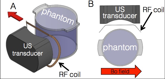
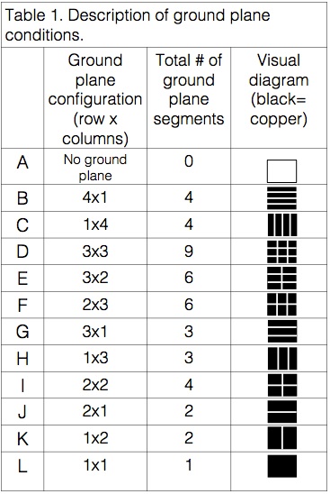
The effects of TGP RF eddy currents were evaluated using a single rectangular RF coil (20cmx13cm) wrapped around a homogeneous cylindrical phantom and a simulated TGP. The phantom was a homogenous (1.955g/L CuSO4) cylinder (12cm diameter x 11cm height). The TGP was simulated by placing copper tape on the face of a 3-D printed plastic transducer (aperture: 13 x 10 cm, 10 cm radius of curvature). To create different TGP configurations, the ground plane was broken into multiple rows and columns of copper patch elements by removing thin copper strips (1 mm wide) in the short and long axis directions (see Figure 1 and Table 1). To minimize gradient eddy currents and maximize RF eddy currents, the phantom, RF coil and TGP were positioned as shown in Figure 1 for all SNR studies, with the RF loop axis perpendicular to the B0 field of the scanner. For each ground plane configuration, the RF coil loop was tuned and matched to 123 MHz with an insertion loss better than -35 dB. Active and preamp detuning were better than -35 dB and -20 dB, respectively. The SNR studies were performed by acquiring 2D GRE images (TR/TE=500ms/10ms, Flip angle=90°, FOV=256x256mm, 1x1mm resolution, 5mm slice thickness on a Siemens 3T PrismaFit scanner) of the phantom with the RF loop and dividing the resulting image by the Standard Deviation of the noise in the oversampled region of the image.Results
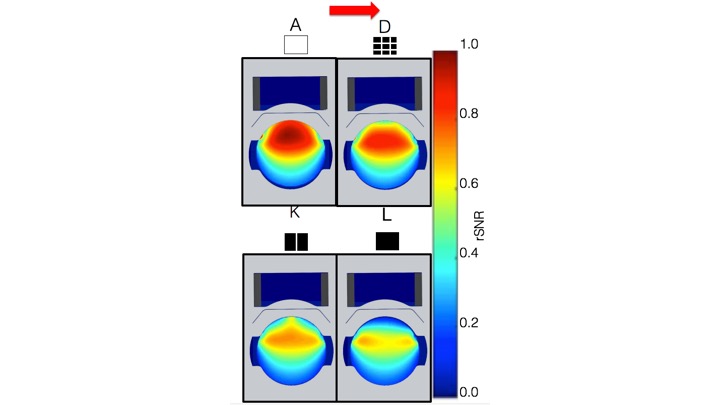
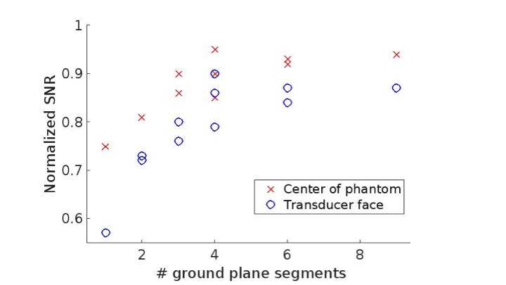
SNR map results of various ground plane conditions are shown in Figure 2. The lack of distortions between SNR plots indicate that the gradient eddy currents were minimized. Relative SNR values for the different TGP configurations are plotted in Figure 3. Using the single element ground plane resulted in a 57% reduction in SNR compared to the SNR with no TGP. As the number of TGP segments were increased, RF eddy currents were reduced resulting in increased SNR.Discussion and Conclusion
This work demonstrates that use of a single continuous TGP in the MRgFUS transducer can result in significant SNR loss. This loss can be dramatically reduced by splitting the ground plane into smaller segments. As seen in Figures 2 and 3, increasing the number of segments in the transducer ground plane increased the relative SNR both at the center of the phantom and at the transducer face for this particular transducer and coil configuration. Since different transducer/sample configurations can have varied effects on SNR, the ground plane configuration should be evaluated at the beginning of the ultrasound transducer design process for a given application. The reduction of RF eddy current effects in the imaging volume will increase image SNR and enhance both anatomic and temperature imaging during MRgFUS treatments.Acknowledgements
Funding was provided by NIH grant R01 CA172787References
1. Lechner-Greite SM, Hehn N, Werner B, Zadicario E, Tarasek M, Yeo D. Minimizing eddy currents induced in the ground plane of a large phased-array ultrasound applicator for echo-planar imaging-based MR thermometry. Journal of Therapeutic Ultrasound. 2016;4:4.
2. Minalga E, Payne A, Merrill R, et al. An 11-Channel Radio Frequency Phased Array Coil for Magnetic Resonance Guided High Intensity Focused Ultrasound of the Breast. Magnetic Resonance in Medicine. 2013;69(1):295-302.
Figures