2520
Assessment of image qualities of multi planar reformatted images depending on imaging planes of a variable refocus flip angle 3D FSE sequence (Cube) in cervical spine MRI1Division of Radiology, Seirei Sakura Citizen Hospital, Sakura, Japan, 2Department of Radiology, Toho University Sakura Medical Center
Synopsis
The purpose of this study is to assess image qualities of MPR images depending on imaging planes of Cube to determine the optimal imaging plane in the cervical spine. The differences of FWHMs in frequency and phase encoding directions of the transverse, sagittal, coronal source images were compared and those encoding directions on the transverse, sagittal, coronal MPR images were compared. MRI of Volunteers image qualities were recorded by assessing sharpness of the vertebral body, spinal cord, and nerve roots on the images. To provide better image qualities in cervical spine MRI using Cube, transverse planes should be selected.
Background/ Purpose
3D FSE sequence (Cube) can provide high-resolution 3D MRI. However, there is no report describing image qualities of multi planar reformatted (MPR) images depending on imaging planes in Cube. The purpose of this study is to assess image qualities of MPR images depending on imaging planes of Cube to determine the optimal imaging plane in the cervical spine MRI.
Materials and Methods
All images were obtained with 3T MRI(Discovery750w; GE Healthcare).
1)Experimental assessment
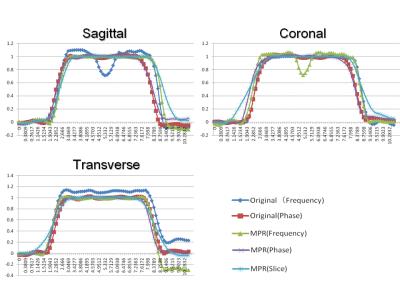
A phantom with 6 mm-beads was made and imaged in transverse, sagittal, and coronal planes by using Cube for assessing the spatial resolution of T2-weighted images. From the transverse, sagittal, and coronal source images, MPR images were also generated in the major three planes. First, the diameters of 6 mm-beads were measured in frequency and phase encoding directions on the transverse, sagittal, coronal source images. In addition, they were also measured infrequency, phase, and slice encoding directions on the transverse, sagittal, and coronal MPR images. Second, the profile curves of the diameters of 6 mm-beads on the images were made. From these data, Full Width at Half Maximum (FWHM) was calculated using the interpolation method. The differences of FWHMs in frequency and phase encoding directions of the transverse, sagittal, coronal source images were compared and those in frequency, phase, and slice encoding directions on the transverse, sagittal, coronal MPR images were also compared.
2)Image assessment
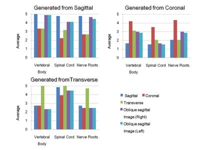
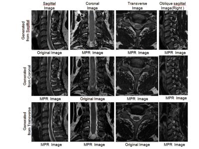
A total of three healthy volunteers were enrolled. MRI was obtained in transverse, sagittal, and coronal planes by using Cube. In addition to transverse, sagittal, coronal MPR images from transverse, sagittal, coronal source images, oblique sagittal MPR images along with the neural foramen of the cervical spine were also generated. Image qualities were recorded by assessing sharpness of the vertebral body, spinal cord, and nerve roots on the images according to 3-grading system by five radiological technologists and one certificated radiologist. Significant difference tests were performed by using a Wilcoxon signed-rank test.
Results
1) Experimental assessment
On both the original source images and MPR images, the smallest difference between the measurements of FWHM on the images and the diameters of the 6mm-beads was found in phase encoding direction compared to in frequency and slice encoding directions.
2) Image assessment
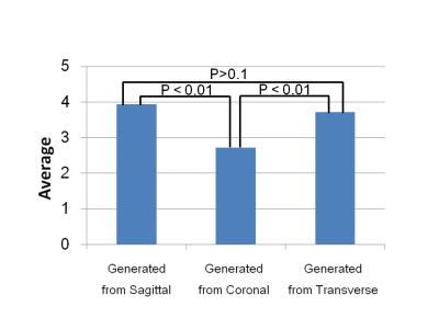
Regarding the sagittal imaging plane, the sharpness of the vertebral body and nerve roots on all the MPR images from the sagittal source images was much higher than that on the others. In contrast, regarding the coronal imaging plane, the sharpness of the vertebral body, spinal cord, and nerve roots on all the MPR images from the coronal source images was quite lower than that on the others. Regarding the transverse imaging plane, the sharpness of the spinal cord was much higher on all the MPR images from the transverse source images than those on the others, but the sharpness of the vertebral body and nerve roots on the sagittal MPR images was lower than that on the MPR images from the sagittal source images.From the results of significant difference tests, there is no statistically significant difference between the image qualities on the MPR images from transverse source images and those from the sagittal source images.However, the image qualities on the MPR images from the coronal source images was quite lower than those on the MPR images from transverse and sagittal source images.
Discussion
The original imaging planes using Cube influenced the image qualities on the MPR images. As the causes, the following two major factors may be considered;
a)Influences by the frequency, phase, and slice encoding directions on image
In the experimental assessment, the differences of spatial resolution in frequency, phase and slice encoding directions were considered to be due to use of parallel imaging technique in phase encoding direction and use of computational image (ZIP)in slice encoding direction.
b)Influences by flow and motion artifacts
In the image assessment, regarding the differences of image qualities on the MPR images from transverse, sagittal, and coronal source images, flow voids can be minimized on the transverse images since a flow compensation technique can be added in slice encoding direction on the transverse images. Motion artifacts can be severe on the coronal source images. Therefore, a transverse plane is considered to be the best imaging plane using Cube. However, to generate isotropic images, the computational image (ZIP) in the slice encoding direction should not to be used.
Conclusion
To provide better image qualities in cervical spine MRI using Cube, transverse imaging planes should be selected instead of sagittal and coronal imaging planes.
Acknowledgements
No acknowledgement found.References
1. Inukai C, Inukai T, Matsuo N, Shimizu I, Goto H, Takagi T, Takayasu M.Usefulness of curved coronal MPR imaging for the diagnosis of cervical radiculopathy. No Shinkei Geka. 2010 Mar;38(3):251-7
2. Yokosawa K, Sasaki K, Muramatsu K, Ono T, Izawa H, Hachiya Y.Visualization of Anterolateral Ligament of the Knee Using 3D Reconstructed Variable Refocus Flip Angle-Turbo Spin Echo T2 Weighted Image.Nihon Hoshasen Gijutsu Gakkai Zasshi. 2016 May;72(5):416-23. doi: 10.6009/jjrt.2016_JSRT_72.5.416.


