2508
An Optimal Design for 32 Channel Head-Neck Coil1Lauterbur Imaging Research Center, Shenzhen Institutes of Advanced Technology, Chinese Academy of Sciences, Shenzhen City, People's Republic of China, 2Department of Radiology and Biomedical Imaging, University of California San Francisco, CA, United States, 3UCSF/UC Berkeley Joint Graduate Group in Bioengineering, San Francisco, CA, United States
Synopsis
In this study, we build an optimized 32 channel head-neck coil array to improve the weak SNR of area behind cervical spine from the previous designed neck-coil array. Two of the original eight neck coils is place to the area near scruff with a new structure. Comparing the optimized 32-channel head neck coil with the previous: imaging test has improved 63% higher than the previous coil array. For g-factor measurement, optimized neck coil array is the same as the previous one. The results indicate that the optimized coil array is better for neck imaging.
purpose
Simultaneous imaging of intracranial and extra-cranial arterial wall would greatly facilitate plaque detection in these two vascular beds. Previous study has proposed 32 channel head-neck coil system1 for joint imaging of intracranial and extra-cranial arterial vessel wall at 3T. However the SNR at cervical spine needs to be improved to for vertebral artery imaging. In this work, we propose an optimized head-neck coil not only keep the high resolution for intracranial and extra-cranial arterial vessel wall, but also increase the SNR for the whole neck.Methods
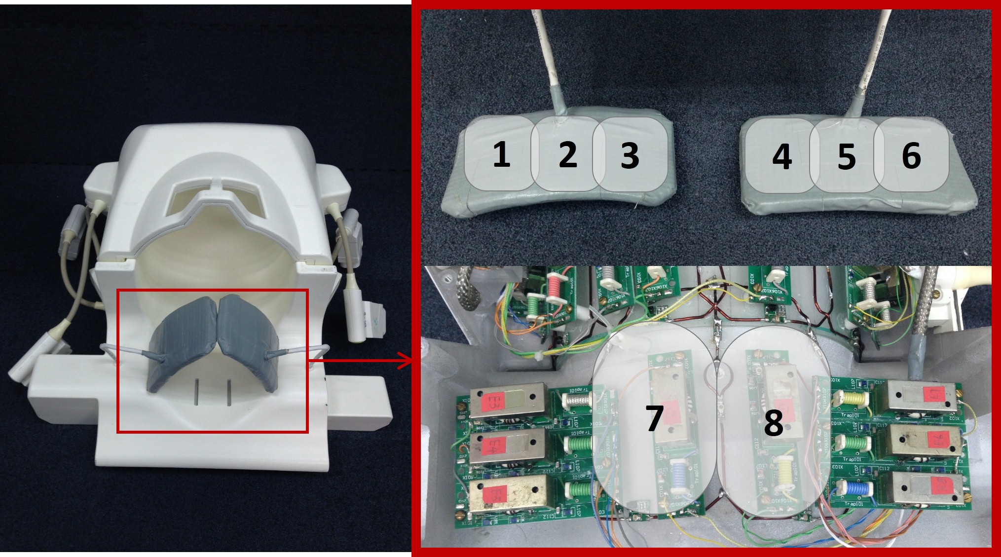
An optimized 32 channel head-neck coil is shown in Figure 1. The optimized head-neck coil contains two parts: 24 elements for intracranial arteries in head region and 8 elements in neck region. The 8 elements in neck consist of two coils with the size of 12.8cm×8.8cm, which share the same holder as the head elements, at the back of cervical spine. The rest of 6 coils (7.5cm in longitudinal direction and 6.5cm in transverse direction) are equally fabricated on two pads, which fully cover the front side of neck as shown in figure 1. The structure of head elements are similar with previous study1.
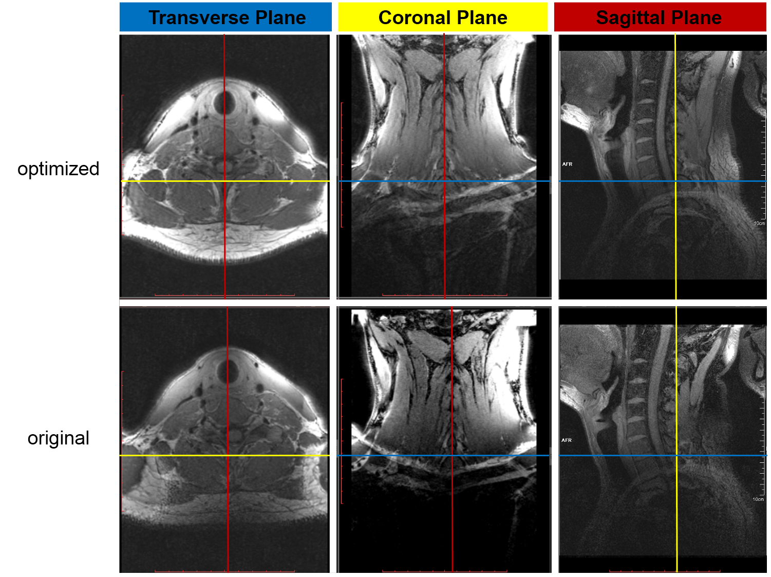
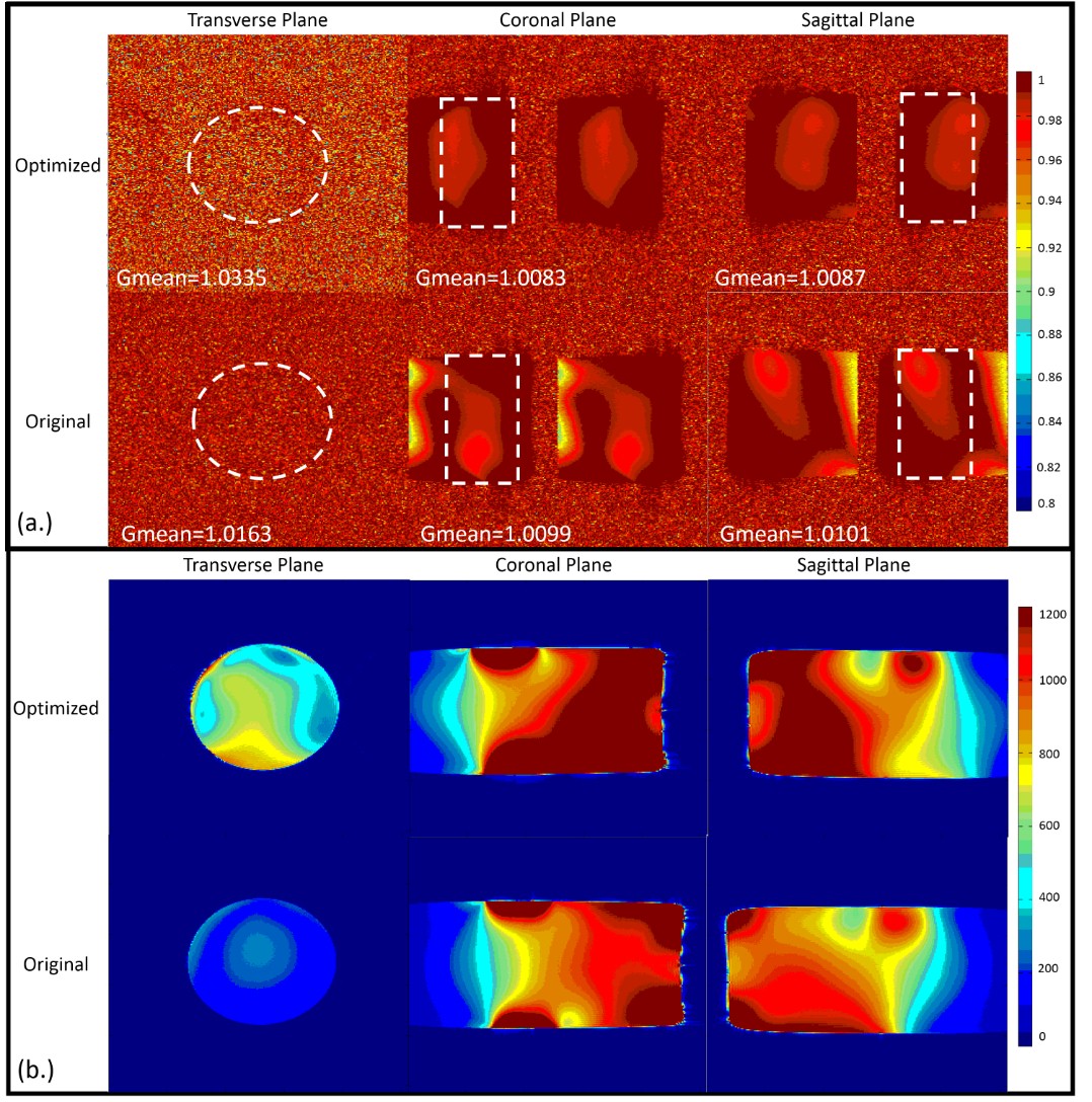
Phantom study: A cylindrical phantom (filled with 1.24g/L NiSO4.6H2O and 2.62g/L NaCl, from Siemens) was used to simulate human’s brain and neck. In order to evaluate the performance of parallel imaging, a gradient echo (GRE) sequence is utilized with following parameter: TR=300ms, TE=10ms, bandwidth=130Hz/pixel, FoV=250× 250mm2, slice thickness=3mm, acquisition matrix=256×256, flip angle=60˚. The PULSAR2 toolbox is utilized to assess parallel imaging performance of the optimized 32 channel head-neck coil. The sensitivity encoding (SENSE3) method is used for imaging acceleration. The phase encoding direction is set to be in the anterior-to-posterior direction with reduction factor R=2. In-vivo study: The volunteers were scanned using each of the two coils with a T1-weighted GRE sequence with the following imaging parameters: TR=12ms, TE=1000ms, bandwidth=595Hz/pixel, FOV= 212×190.6mm2, slice thickness=0.62mm, acquisition matrix=336×336. The same GRE sequence was also used in phantom study to compare the SNR of the two coils. Noise was measured using the same sequence with the excitation pulse’s voltage set to zero.
Results
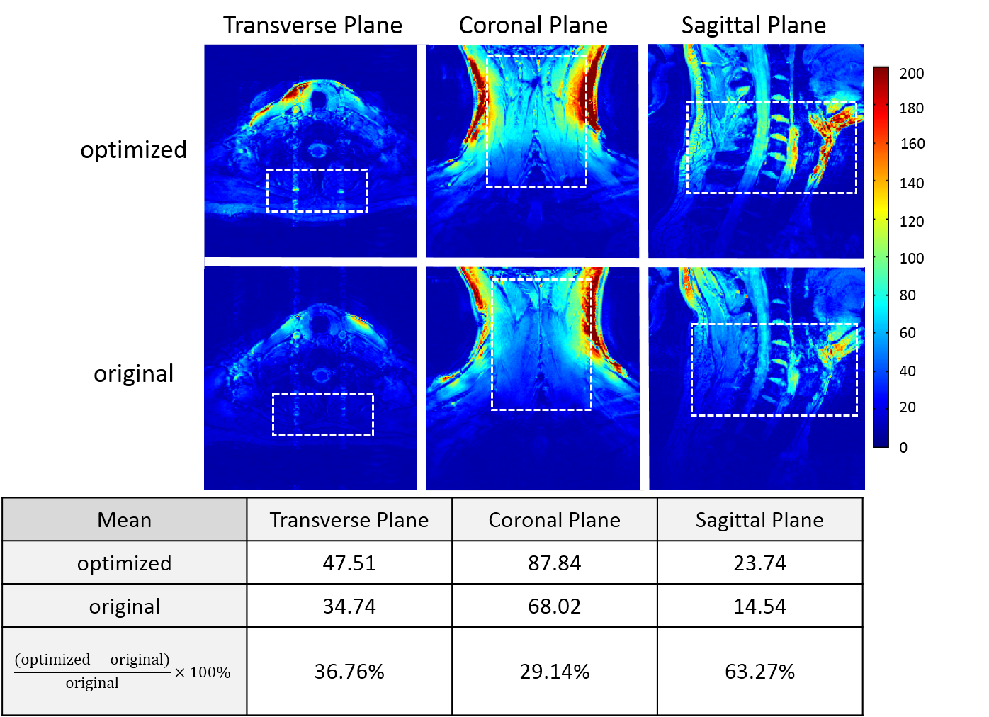
The g-factor map and SENSE image shown in Figure 4 indicate that optimized has better capability for parallel imaging than the original designed channel. Our coil shows more details and offers better sharpness of image than the original one as illustrated in Figure.4. For SNR, we compare the SNR map with the older one slice by slice, and notice that at the position of cervical spine our coil is 63% better.Discussion / Conclusion
In this work, an optimized 32-channel RF coil array for head and neck vascular imaging at 3T was presented. With the re-design, the optimized 32-channel head and neck coil array has demonstrated the improvement in not only SNR near carotid artery and cervical spine, but also the capability of parallel imaging over the original 32-channel head and neck coil array, providing a better RF hardware solution to head and neck vascular imaging at 3T. This work shows once again that different imaging applications need different RF hardware solutions. A one-fits-all solution usually does not work in MR imaging applications if the applications need high performance imaging, especially in the peripheral brain regions.Acknowledgements
This work is supported in part by national key R&D programno. 2016YFC0100100, national grants no. 51307171, 61571433,61401450, 81470077 and 2013CB733800/2013CB733803, provincialgrants no. 2015B020214006 and 2014A030310200, city grant no.KQJSCX20160301143250, CYJ20140417113430589,JSGG20141020103440414 and internal grant no. 201314.The authors thank Prof. Wu Jun. and Wang Tingting at PekingUniversity Shenzhen Hospital, Prof. Ren Lijie and Cai Jingjing at the2nd People's Hospital for their help in patient recruitment.References
[1] X Hu, et al., MRI, 2017, 36(2): 86-92. [2] Pruessmann KP, et al., Magn Reson Med 1999; 42(5):952-962. [3] Ji JX, et al. Concept Magn Reson B, 2007;31B(1):24-36.Figures