2462
Design of a 24-channel array for imaging Intracranial vascular wall at 3TJo Lee1, Xiaoqing Hu1, Lei Zhang1, Xiaoliang Zhang2,3, Xin Liu1, and Ye Li1
1Lauterbur Imaging Research Center, Shenzhen Institutes of Advanced Technology, Chinese Academy of Sciences, Shenzhen City, People's Republic of China, 2Department of Radiology and Biomedical Imaging, University of California San Francisco, CA, United States, 3UCSF/UC Berkeley Joint Graduate Group in Bioengineering, San Francisco, CA, United States
Synopsis
Atherosclerosis is a major cause of ischemic stroke. In this study we build a 24-channel head coil array with a special designed coil arrangement to detect non-stenotic atherosclerotic plaques. We compare the 24-channel head coil with Siemens 32-channel coil. For imaging test, the g-factor maps of these two coil arrays are the same, which shows that the 24-channel coil has the same capability of paralleling imaging as the 32-channel coil, and SNR maps show that at the center of the phantom which corresponds to the intracranial region of the head, the 24-channel coil is as good as 32-channel coil.
purpose:
Atherosclerosis is one of the major causes of ischemic stroke, while traditional method, such as luminal angiography detection, often misses the non-stenotic atherosclerotic plaques due to their small physical size. High resolution magnetic resonance imaging (MRI) of vessel wall by using highly sensitive multi-channel RF coil arrays is critically important in detecting those small lesions. This work aims to build a 24-channel head coil to detect the non-stenotic atherosclerotic plaque.Methods and Materials:
A 24-channel head coil array based on the traditional lumped-element technology is designed and constructed to image the regions of MCA (middle cerebral artery) and ICA (internal carotid artery) at 3T. The photograph of the prototype coil array is shown in Figure 1. For comforting patients to lie in, 24-channel head coil structure was designed into anterior and posterior part. 10 elements were used for the anterior part, while other 14 elements were used for the posterior part as shown in Figure2. All 24 coils arrays were made in 11cm 11.5cm rectangle shape to cover whole area, and the structure was based on the design of NMR phased array2.The rest 10 coil array were places on the upper shell, the proposed 24-channel coil array was tested through MR imaging in both phantoms and humans on a 3T MR scanner. The imaging performance in terms of SNR and parallel imaging capability was compared with a commercial 32-channel head coil with the similar physical size. Phantom study: A Siemens spherical phantom (filled with 1.25g NiSO4.6H2O per 1000g H2O) measuring 175 mm in diameter is used to evaluate the coil sensitivity over an area of interest large enough to cover the head and neck. In imaging experiments, we use a gradient echo (GRE) sequence with the following parameters for imaging acquisition and also for calculating g-factor maps: TR=300ms, TE=10ms, Bandwidth=130Hz/pixel, FOV=250×250mm2, Slice thickness=3mm, Acquisition matrix = 256×256, Flip angle=60˚, Slice number=1, Measurement=1. The sensitivity encoding (SENSE3) method is used for imaging acceleration. The phase encoding direction is set to be in the anterior-to-posterior direction with reduction factor R=2.Images in the sagittal and coronal orientations were acquired. Noise images were also acquired by setting transmit voltage to zero on the scanner. We reconstructed the images by exploiting the method called root sum of squares (Cov-SoS). SNR maps were calculated based on reference3. In-vivo study: T1w-SPACE sequence was used to acquire 3D images with following parameters: TR=14ms, TE=800ms, Bandwidth=504Hz/pixel, FOV=160×160mm2, Slice thickness=0.6mm, Acquisition matrix=320×320, Slice number=1, Measurement=1, iPAT=2. In the performance comparison studies of the proposed 24-channel head coil and the commercial 32-channel head coil, experiment setup and all imaging parameters were kept same in order to have a fair meaningful comparison.Results
Figure 2 shows the SNR maps of the proposed 24-channel head coil and the commercial 32-channel head coil (Siemens Medical Systems) in three different orientations. The ROI for MCA and ICA is drawn in the figure. We calculated the mean and standard deviation from those, the results show that the mean of SNR from the 24-channel coil is 10% lower than Siemens 32-channel coil. Figure 3 illustrates that at the ROI of MCA and ICA, the 24-channel coil achieves similar SNR and signal intensity distribution, at the same spatial resolution, over the 32-channel coil. The g-factor maps shown Figure 4 demonstrate that the 24-channel coil has slightly better ability for integrated parallel imaging than the commercial 32-channel head coil at the acceleration rate = 2.Discussion/Conclusion
In this study, a 24-channel head coil array for intracranial vascular wall imaging at 3T has been constructed and tested. In the region of interest, i.e. middle cerebral artery and internal carotid artery, the proposed 24-channel head coil array demonstrates a comparable performance in SNR over the commercial 32-channel head coil array. This might result partially from the enlarged coil size of each array element of the 24-channel coil array. When combining with an appropriate neck coil, this 24-channel head coil array could be a better choice for detecting atherosclerosis plaques4.Acknowledgements
This work is supported in part by national key R&D programno. 2016YFC0100100, national grants no. 51307171, 61571433,61401450, 81470077 and 2013CB733800/2013CB733803, provincialgrants no. 2015B020214006 and 2014A030310200, city grant no.KQJSCX20160301143250, CYJ20140417113430589,JSGG20141020103440414 and internal grant no. 201314.The authors thank Prof. Wu Jun. and Wang Tingting at PekingUniversity Shenzhen Hospital, Prof. Ren Lijie and Cai Jingjing at the2nd People's Hospital for their help in patient recruitment.References
Wang XY, et al., Proc Intl Soc Mag Reson Med 2012;20:2787. [2] Roemer PB, et al. Magnet Reson Med 1990;16(2):192-225. [3] Keil B, et al., J Magn Reson 2013; 229:75-89. [4] X Hu, et al., MRI, 2017, 36(2): 86-92.Figures
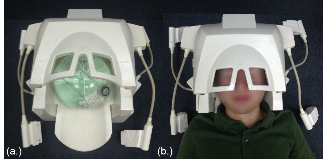
The outward appearance of 24 channel head coil.
(a.) with phantom (b.) with volunteer
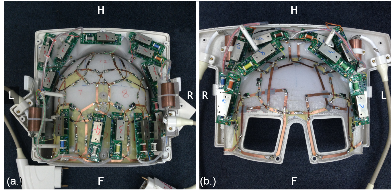
The soccer-ball design of 24-channel coil array
structure (a.) 14 coil arrays for the bottom-side, and (b.)10 coil arrays for
the upper side
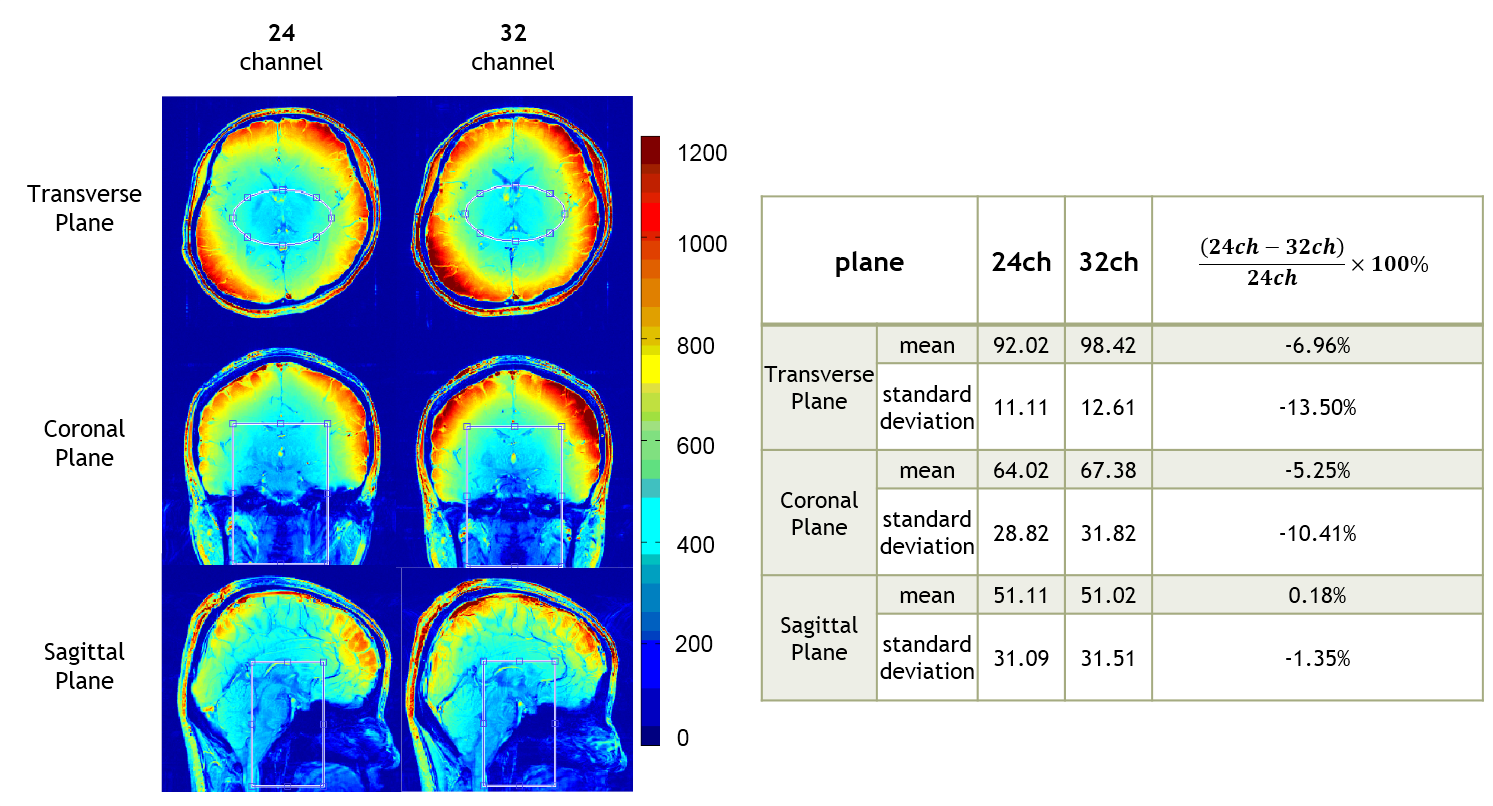
The SNR map of both 24 channels head coil and 32
channels head coil on transverse, coronal and sagittal orientations. The table
shows the mean and standard deviation of ROI (middle cerebral artery region and
internal carotid artery region) from each slice.
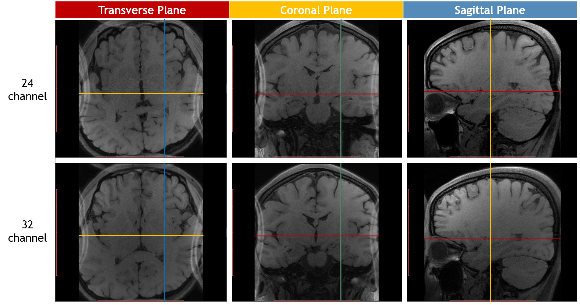
3D T1 weighted images of the whole human brain
with 0.6 mm × 0.6 mm × 0.6 mm resolution in totally 10 minute 12 second. Each
color lines represent the location of the corresponding color plane.
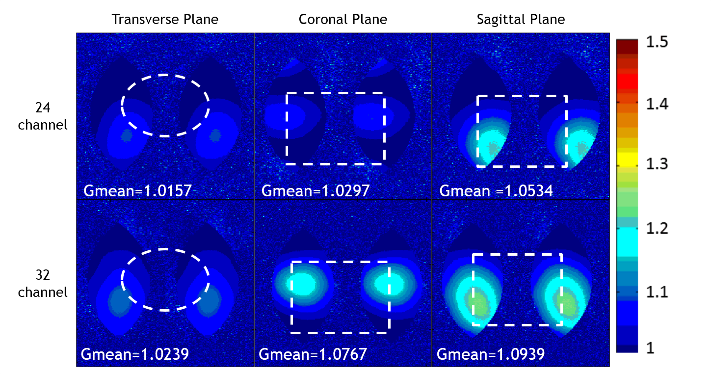
g-factor map of 24-channel head coil and
32-channel head coil at SENSE R=2.