2413
A modular RF coil platform for ex-vivo imaging of brain slices at 9.4T1Dept. of Cognitive Neuroscience, Faculty of Psychology and Neuroscience, Maastricht University, Maastricht, Netherlands, 2Lab Engineering & Instrumentation Department, Maastricht University, Netherlands, 3Scannexus, Maastricht, Netherlands
Synopsis
We present a modular 9.4T RF coil platform that can be used for imaging slabs of tissue as large as a sagittal section of a human brain (dia. 18cm), with a thickness of up to 2cm. The 23-channel receive array was designed with a layered printed circuit approach to ensure the coils’ decoupling and proximity to the sample and with on-coil, low-noise preamplifier circuits. A 7 channel, phased transmit array capable of parallel transmission (pTx) makes homogeneous excitation of a large range of samples possible. The high homogeneous contrast-to-noise acquisitions enabled by the coil will allow high resolution anatomical imaging at 9.4T.
Introduction
RF array coils designed for in-vivo imaging are not well suited to imaging ex-vivo brain samples. This holds especially true for imaging flat slabs or sections of brain tissue which would otherwise have a poor filling factor and/or relatively large distances between the coils and the sample. Previously, we showed the results of using a cylindrical phased-array receive (Rx) RF-coil to image large non-flat specimens (~80x80x80mm3) at very high resolutions using a large-bore human 9.4 T MRI system1. Here, we present a modular 9.4T RF coil platform that can be used for imaging slabs of tissue as large as a sagittal section of a brain hemisphere (dia. 18cm), with a thickness of up to 2cm, which can then be used for post-imaging histological analysis,. A layered approach2 was used while designing the receive array to ensure the coils’ proximity to the sample under investigation.Methods
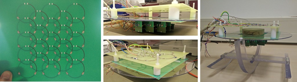
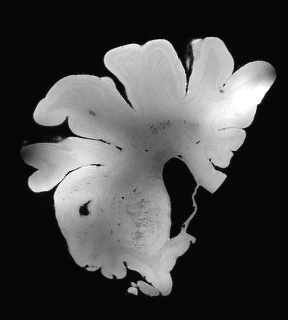
The receive array consists of 23 individual circular elements, each 4 cm in diameter. Each receive loop is split into 3 equal arc segments, with each segment occupying a different layer in the 4-layer PCB (Rogers Corp, Gent, BE), and individual coil segments connected with vias (Fig 1L). This allows us to effectively overlap all coil elements without compromising on mutual decoupling3, while also allowing for a flat surface on which to place our sample for imaging, thereby ensuring an optimised filling factor for the coil. The coils are connected to dedicated on-coil, low-noise preamplifier circuits which also include a balun circuit with a tuning/matching network, preamplifier decoupling and receiver detuning circuitry. For our initial tests, 16 central loops were populated and tuned and matched to 399.7 MHz. A separate 7 channel, phased transmit array was first simulated in CST (Computer Simulation Tech, Darmstadt, DE) to determine ideal field patterns and then milled on a 1.5mm thick FR4 board. All transmit coils were tuned to the same Larmor frequency and connected to an 8-channel Step2 plug capable of parallel transmission (pTx). The sample holder was designed using SolidWorks and 3D printed using SOMOS Watershed XC11122 (DSM Heerlen, NL) material, which has susceptibility close to that of water, thus helping us reduce any susceptibility mismatch effects. The sample used was a 8cm wide, 1cm thick coronal slab from a post-mortem brain, preserved in a proton-free, susceptibility matching fluid (Fluorinert FC-3283) and placed inside the container, which was then sealed using a vacuum sealing paste. (Dow Corning, MI, USA). The entire coil assembly is supported on a semi-circular plexiglass chassis such that the sample rests at the magnet isocenter (Fig 1R). The transmit and receive coils are separated by adjustable spacers which would allow us to accommodate samples of varying thicknesses. Images were acquired using a Gradient Echo sequence at 250μm isotropic (TR/TE = 23ms/6.21ms, FOV = 80mm, flip angle = 20˚, Bandwidth = 120 Hz/px) in an 820mm bore human 9.4T magnet equipped with an 80mT/m maximum amplitude gradient set (Siemens MAGNETOM 9.4T with AC84mkII).Results & Discussion
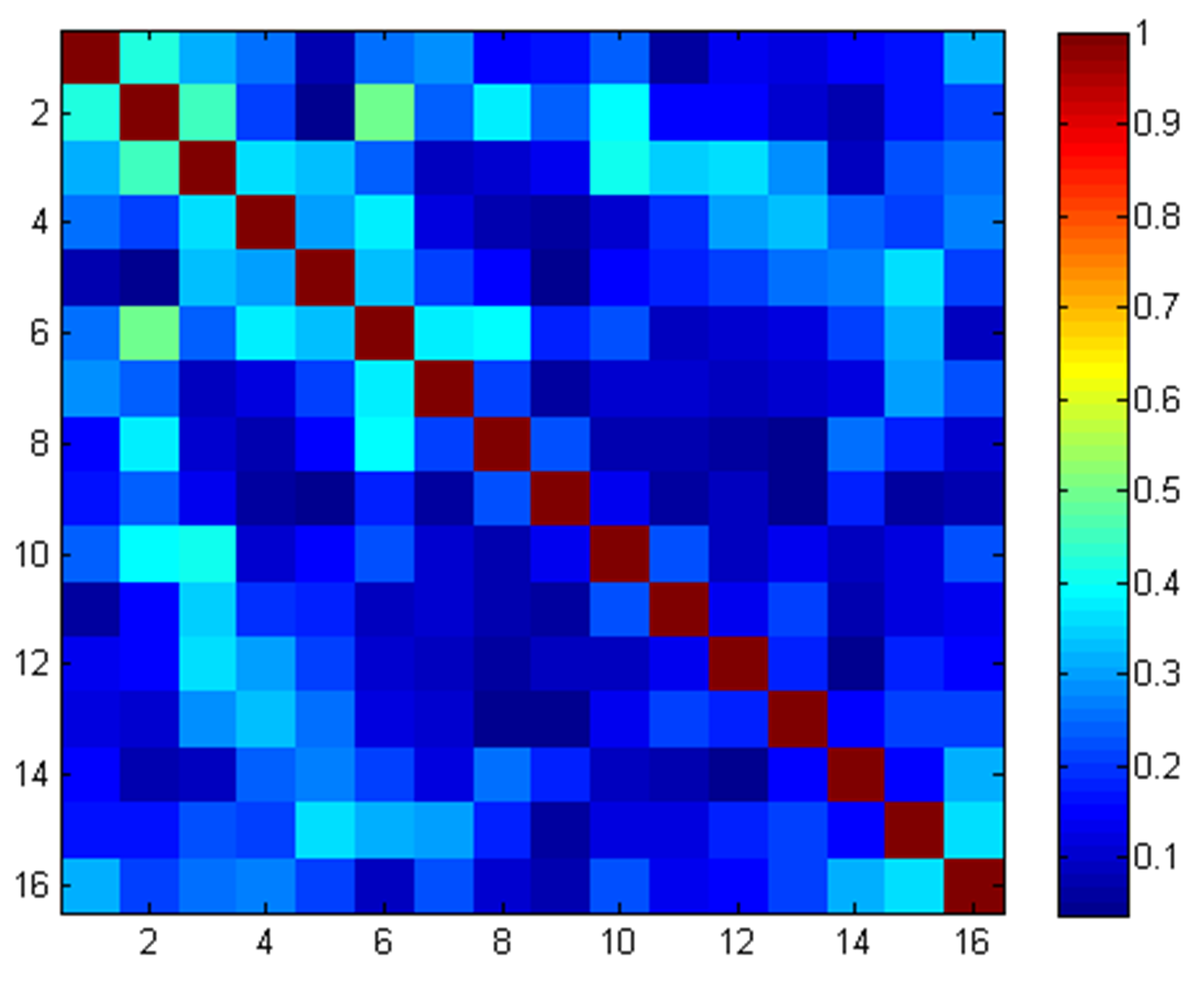
For the receive array, the loaded reflection coefficient was better than -19dB. Preamplifier decoupling between adjacent coil elements was -22dB or better. The receive array had a maximum noise correlation of 0.48 and an average of 0.18 (Fig 2). The transmit coils had a loaded reflection coefficient of -16dB or better. Inter-element decoupling between pairs of transmit coils was -12dB or better. The resulting 250μm isotropic data shows a relatively homogeneous B1+ field, which falls off towards the periphery of the sample. However, this can be corrected with better B1+ shimming or by using kT-points technique for a more homogeneous sample excitation.Conclusions
We present an imaging platform comprising of a dense phased array receive coil and a separate phased array transmit coil, capable of accommodating post-mortem tissue slabs of up to 2cm thick, for high resolution anatomical imaging at 9.4T. Further work will include populating the remaining receive channels and undertaking higher resolution anatomical imaging.Acknowledgements
No acknowledgement found.References
1. Gruschke, O., et al., Lab on a chip phased-array MR multi-platform analysis system. Lab Chip, 2012,12, 495-502
2. Sengupta, S., et al., High resolution anatomical imaging of the human occipital lobe with a large ex-vivo 9.4T RF coil. Proc 24th ISMRM: #1163 (2016)
3. Roemer, P. B., et al., The NMR phased array. Magnetic resonance in medicine 16(2): 192-225. (1990).
Figures