1952
Current density imaging using novel carbon electrodes proposed for Deep Brain Stimulation (DBS)1School of Biological and Health Systems Engineering, Arizona State University, TEMPE, AZ, United States
Synopsis
Deep Brain Stimulation (DBS) is popular in the treatment of movement disorders. Conventional metal DBS electrodes present MR safety and susceptibility problems. We implemented novel carbon fiber electrodes that produced low susceptibility artifacts for imaging DBS current densities at 7 T. We used Magnetic Resonance Electrical Impedance Tomography (MREIT) to measure the z-component of the magnetic flux density (Bz) resulting from DBS-like pulses and reconstructed projected current density maps (JP) in two objects (agarose-gelatin phantom and ex-vivo piglet brain). We did not observe susceptibility artifact, and reconstructed projected current density maps agreed with simulation in the electrode neighborhood.
Introduction
Deep Brain Stimulation (DBS) of the subthalamic nucleus (STN) is increasingly used in the treatment of movement disorders, principally Parkinson's disease1. Images of current distributions caused by DBS can be used to estimate volumes of tissue influenced by stimulation, informing safety, efficacy and mechanism studies better than computational models. DBS current flow can be imaged using magnetic resonance electrical impedance tomography (MREIT) methods. However, susceptibility artifacts around conventional DBS electrodes are an inherent challenge to this goal2. We demonstrate novel carbon fiber electrodes with low susceptibility artifact for imaging DBS-created electric fields and current densities in the immediate neighborhood of electrodes at 7T.Purpose
1. Novel carbon fiber electrodes with reduced MR susceptibility were fabricated for DBS.
2. The distribution of current injected by carbon electrodes in a DBS setting was mapped using MREIT.
Methods
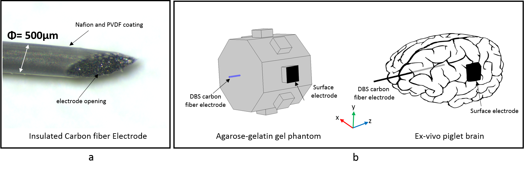
Carbon fiber electrode (CF): Carbon fiber bundles (TC-33 3K filaments, Formosa Plastics Group) were coated with a mixture of Nafion and Isopropanol (1:1). After drying for 12 - 24 hours, the bundles were coated with solutions of Polyvinylidene Fluoride (PVDF) in Acetone (15% (W/V) and 18% (W/V)) until insulation was ensured (figure 1(a)). The impedance of CF electrodes (diameter ~500 microns) measured using an impedance analyzer (HP4192A LF) was ~1kΩ at 1 kHz.
Experimental setup: Imaging experiments were conducted using a CF electrode implanted in both an agarose-gelatin phantom and an ex-vivo piglet brain. A guide needle was used to ensure the orientation of the CF electrode was along the axis of the main magnetic field in both cases. A surface, return electrode (HUREV Co. Ltd, South Korea) of size 10×10 mm2 was attached to the phantom surface and the piglet brain. The orientation of electrodes inserted into each experimental object (phantom and brain) inside the MRI scanner is shown in figure 1(b). Current pulses were injected using a custom-designed MREIT constant current source3 (500µA amplitude and 12ms injection time (Tc)). DBS current pulses were synchronized with a multi-spin echo sequence via the spectrometer generated TTL control pulses. MR data was collected in separate positive (I+) and negative (I-) current injection scans and combined to form magnetic flux density images.
Phantom: The octagonal phantom (20 mm side, 42 mm height) was filled with agarose-gelatin gel (5.2 g/L NaCl, 20g/L Agarose, and 50 g/L Gelatin). The conductivity of the gel measured by a four-probe method using an impedance analyzer (HP4192A LF) was ~1 Sm-1 at 1 kHz.
Brain: A brain was harvested from a healthy 3-day old piglet and preserved in neutral buffered formalin (10%). The brain was soaked in chilled artificial cerebrospinal fluid (ACSF) for 48 hours prior to imaging.
Imaging Parameters: MR Imaging was performed using a 7T Bruker Biospin MRI (Billerica, MA) with bore diameter 20cm, located at the BNI, AZ, USA. Imaging parameters were: Field of view = 80x80 mm2, matrix size = 128×128, TR/TE = 1000/24 ms, slice thickness = 3mm, averages = 2, Tc= 12ms, and total scan time = 256s.
MR data processing: Magnetic flux density (Bz) was calculated using the phase shift induced by positive and negative DBS current pulses4. Subtraction of phase due to I+ and I- cancelled the effect of systematic phase artifact. Projected current density maps (JP) were reconstructed from Bz images using the method proposed by Park et al5.
Results
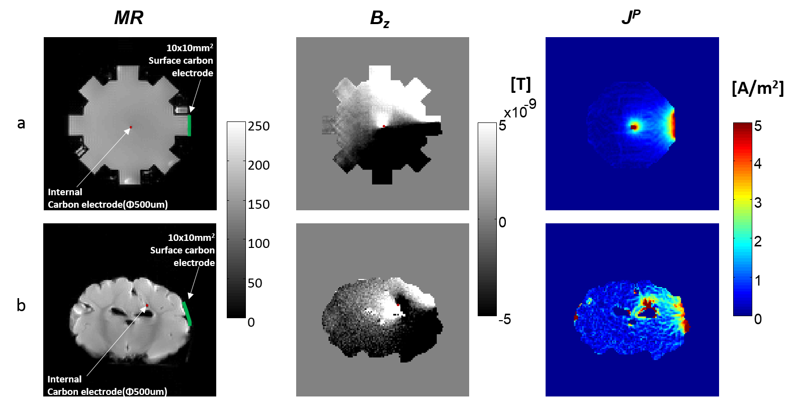
Figure 2 (first row) shows the MR magnitude, Bz and computed projected current density maps (JP) in the gel phantom. Similarly, figure 2 (second row) shows the results in the brain. The position of CF and surface electrodes are indicated in magnitude images with a red dot and green line respectively.Discussion
Typically, the difference in susceptibilities between metal DBS electrodes and surrounding tissues is the major cause of artifacts in imaging of DBS patients. The imaged diameter of CF electrodes was not observed to be greater than actual diameter at this resolution, suggesting little susceptibility artifact (pixel size: 0.625×0.625 mm2; CF diameter: 0.5 mm) compared to metal DBS electrodes. Artifacts in phase and calculated current density images were avoided by ensuring the carbon fiber electrode (CF) aligned with the main magnetic field (B0). The lack of artifact allowed reconstruction of projected current density distributions in voxels immediately surrounding the electrodes.Conclusion
In this study, we used novel carbon electrodes (CF) with low susceptibility artifact in a DBS setting. The relative L2-error between the simulated noiseless current density (J) and estimated projected current density (JP) was 0.23 in the gel phantom. Further studies will involve multiple current injection sites on carbon fiber electrodes for bipolar stimulation.Acknowledgements
Research reported in this publication was supported by the National Institute of Neurological Disorders and Stroke of the National Institutes of Health under Award Number R01NS077004 to RJS.References
1. Tarsy D, Vitek JL, Starr PR et al. Deep Brain Stimulation in Neurological and Psychiatric Disorders. Humana Press.2008.
2. Dunn JF, Tuor UI, Kmech J et al. Functional Brain Mapping at 9.4T using a new MRI compatible electrode chronically implanted in rats. Magnetic Resonance in Medicine. 2009; 61(1):222-228.
3. Oh, T. I., et al. Improved current source design to measure induced magnetic flux density distributions in MREIT. Journal of Biomedical Engineering Research. 2006; 27:30-37.
4. Woo EJ, Seo JK. Magnetic resonance electrical impedance tomography (MREIT) for high-resolution conductivity imaging. Physiol. Meas. 2008;29(10):1–26. $$$
5. Park C et al. Analysis of recoverable current from one component of magnetic flux density in MREIT. Phys. Med. Biol. 2007; 52(11)3001–3013.
Figures