1607
Characterization of Through-Plane and In-Plane Artifacts using a 3D-Printed Grid Phantom with an Embedded Metal Hip Implant1Robarts Research Institute, London, ON, Canada, 2Department of Medical Biophysics, University of Western Ontario, London, ON, Canada, 3Department of Surgery, University of Western Ontario, London, ON, Canada
Synopsis
Metal Artifact Reduction (MAR) is required for orthopedic imaging near implants. Novel MAR techniques have been developed in the past decade, creating a need for quantitative evaluation of the effectiveness of geometric distortion correction. We have developed a 3D-printed modular conformal grid phantom, consisting of a grid of regularly spaced spherical markers. This phantom provides a measure of inherent field inhomogeneity, and contains a conformal cavity in which a metal object can be embedded. This approach provides a means to characterize through-plane and in-plane artifacts across a 3D volume, facilitating testing and validation of novel MAR techniques during development.
Introduction
MRI is commonly used to
detect soft-tissue damage associated with orthopedic implants; however, the
difference in magnetic susceptibility between metals and tissue gives rise to
substantial magnetic field inhomogeneity, leading to image artifacts. Techniques
to reduce these metal artifacts have been demonstrated,1-11 however, most previous outcome analyses rely on
qualitative analysis of clinical cases. Quantitative analysis of metal
artifacts with geometric markers has been limited to planar phantoms, which allows
for characterization of only a single slice.12,13 Phantoms have been developed for volume characterization of inherent
field inhomogeneity using 3-dimensional grids of fiducial markers,14-17 but have not been adapted with the ability to evaluate metal artifacts in
3D. To address the need for evaluation of metal artifact reduction (MAR) techniques
we present a method to 3D-print a phantom that provides fiducial markers completely
surrounding an embedded object, facilitating volumetric characterization of
artifacts caused by the B0 field inhomogeneity induced by metal artifacts. We
demonstrate the phantom design with an embedded hip implant, comprised of a
titanium stem (χ=18218) and cobalt-chrome head (χ=130018).
Methods
Design of modular conformal grid phantom:
The phantom design is based on that of Holdsworth et al., who 3D-printed spherical markers on thin supports and morphologically eroded them to create a quantitative map of image distortion over a 3D volume.19 Our phantom is designed to be printed in Polylactic Acid (PLA) using Fused Deposition Modelling (FDM). To validate this printing method, we fabricated a test grid and analyzed the marker spacing throughout the phantom using micro-CT; we also characterized the magnetic susceptibility of PLA using a dual-echo field map.
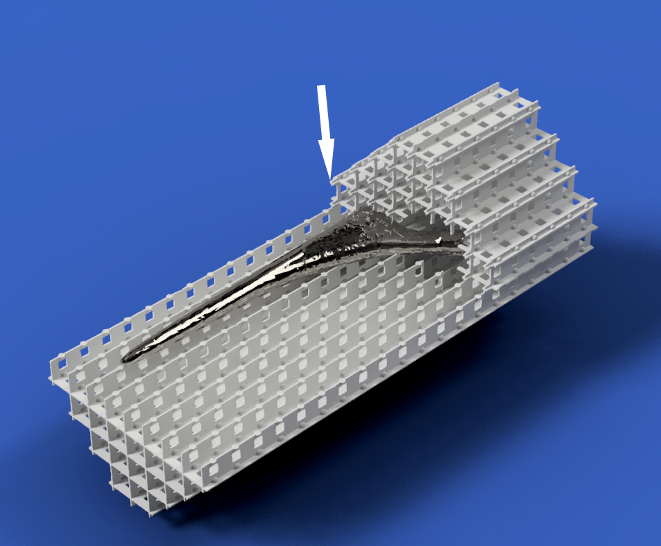
The phantom was created using computer-aided design (CAD) with a rectangular pattern of repeating cells consisting of a single 4.5 mm spherical marker and 0.8 mm supporting walls. To enable an implant to be embedded into the 3D phantom, the grid phantom must be fabricated from several interlocking conformal modules. Therefore, to ensure that accurate and known ball-marker spacing is maintained once the modules are assembled, tight fitting “clips” were designed and integrated into the interfaces of the separate modules. (Fig. 1). For the hip implant evaluated, the phantom was fabricated from three modules. The geometry of the implant was derived from a micro-CT image (120 kVp, 360 µm voxels). The implant surface geometry was saved as an STL file and imported into the CAD program, where it was converted to a solid object and subtracted from all three grid-phantom modules, thereby creating conformal cavities (Fig. 2).
Phantom fabrication and assembly:
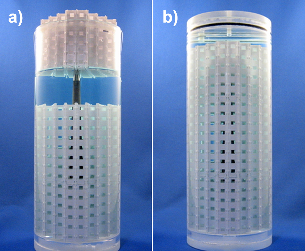
All three modules were 3D printed; the implant was inserted into the middle module and the remaining modules were pressed to complete the assembly. The phantom was then inserted into a cylinder containing CuSO4 solution20 (Fig. 3) and evacuated of air.
Imaging and evaluation:
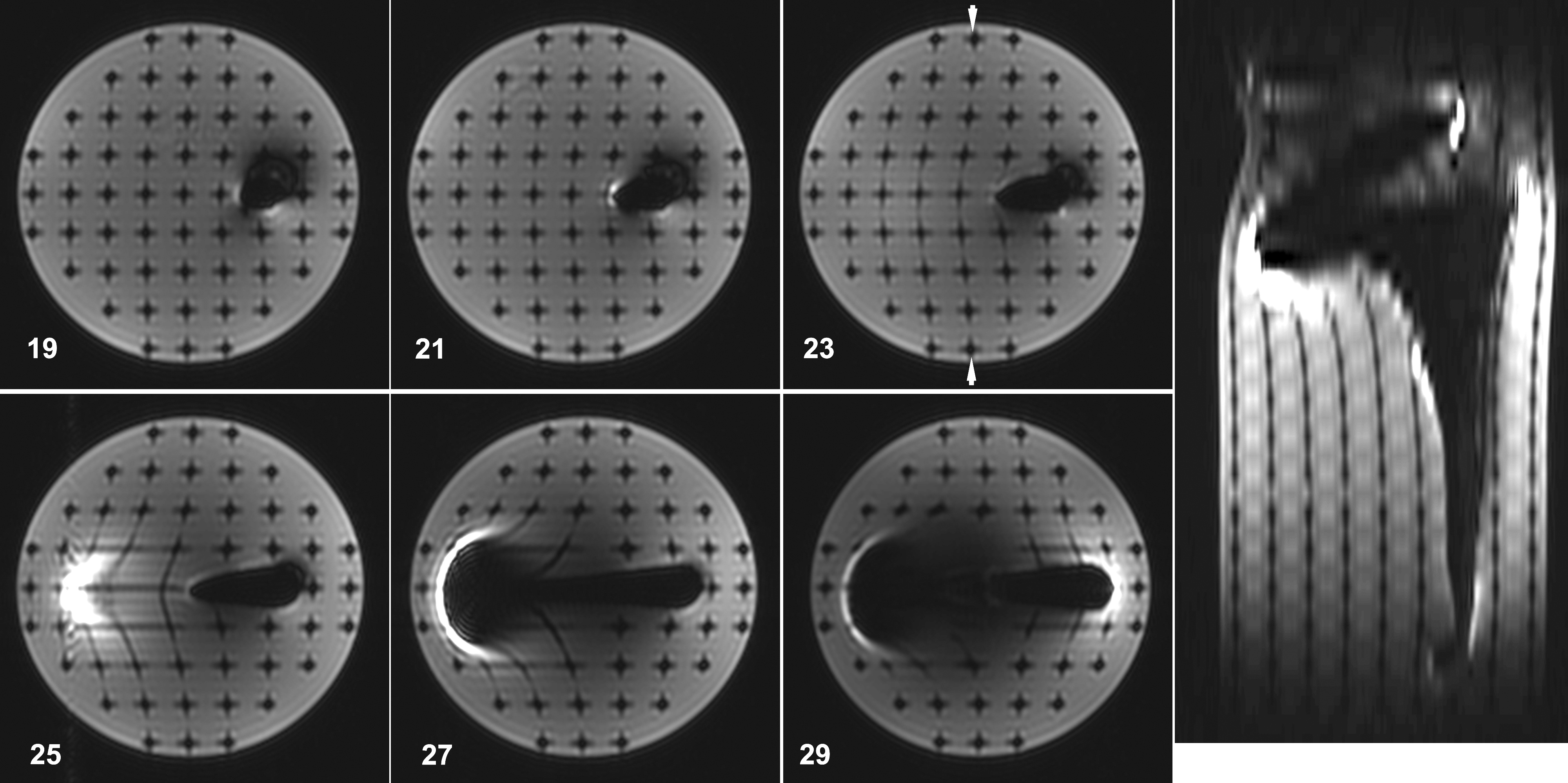
Axial images were acquired with 3 mm slices separated by 3.5 mm, bisecting the planes of spherical markers and the midpoints between them, using a clinically relevant sequence (3T, knee coil, FSE-STIR, TE=50 ms, matrix=320x192, 40 slices, NEX=2, BW=41.67). In-plane distortions were analyzed by comparing the spacing of the centroids in the image with the known spacing of the markers and through-plane distortions were observed through the presence or absence of markers, depending on the slice location.
Results
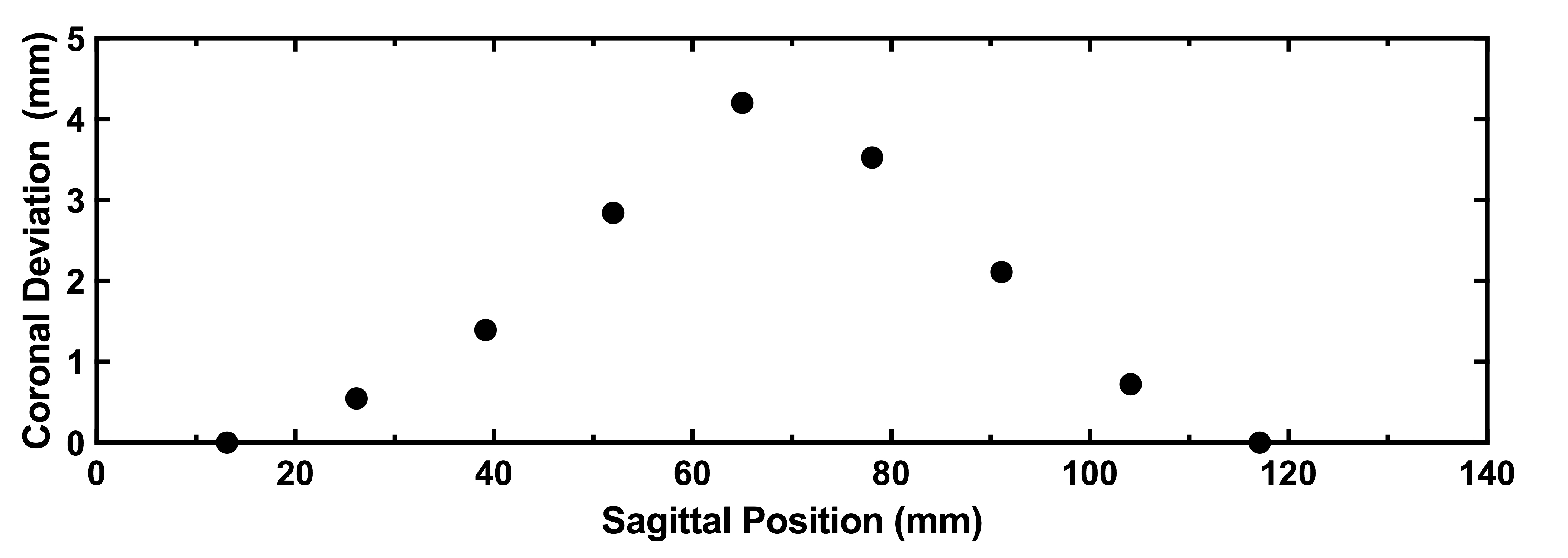
Validation studies showed that the test grid exhibits centroid deviations with mean magnitude of 0.13±0.06 mm and a maximum frequency shift under 2 ppm. Figure 4 demonstrates the ability of the phantom to characterize distortions in 3D. Image analysis of the the spherical markers shows in-plane deviation from their expected spacing throughout the axial slices, with minor deviations surrounding the titanium stem and severe in-plane and through-plane distortions surrounding the cobalt-chrome head. Figure 5 quantitatively illustrates deviations of up to 4.6 mm near the implant stem.Discussion and Conclusions
The ability to characterize and evaluate metal artifacts is crucial for the validation and advancement of novel MAR techniques. We present a cost-effective, customizable solution that provides quantitative geometric measurements across a three-dimensional volume. The regular 3D array of markers allows for in-plane and through-plane distortions to be easily observed in image slices. In-plane marker deviation can be analyzed to characterize distortion, including regions of the image in close proximity to the metal object. The design flexibility granted by fabricating the grid in parts allows for a wide array of embedded test subjects, with minimal loss of fiducial markers. Future research in metal artifact reduction can make use of this phantom design to robustly and inexpensively test and validate novel techniques, which will improve development in the field.Acknowledgements
The authors would like to thank Hristo Nikolov and Alex Kopacz for their assistance in fabricating the phantom as well as Junmin Liu for assisting in image analysis.References
1 Koch, K. M. et al. Imaging near metal with a MAVRIC-SEMAC hybrid. Magnetic resonance in medicine 65, 71-82, doi:10.1002/mrm.22523 (2011).
2 Toms, A. P., Smith-Bateman, C., Malcolm, P. N., Cahir, J. & Graves, M. Optimization of metal artefact reduction (MAR) sequences for MRI of total hip prostheses. Clinical radiology 65, 447-452, doi:10.1016/j.crad.2009.12.014 (2010).
3 Ai, T. et al. SEMAC-VAT and MSVAT-SPACE sequence strategies for metal artifact reduction in 1.5T magnetic resonance imaging. Investigative radiology 47, 267-276, doi:10.1097/RLI.0b013e318240a919 (2012).
4 Sutter, R., Ulbrich, E. J., Jellus, V., Nittka, M. & Pfirrmann, C. W. Reduction of metal artifacts in patients with total hip arthroplasty with slice-encoding metal artifact correction and view-angle tilting MR imaging. Radiology 265, 204-214, doi:10.1148/radiol.12112408 (2012).
5 Ulbrich, E. J., Sutter, R., Aguiar, R. F., Nittka, M. & Pfirrmann, C. W. STIR sequence with increased receiver bandwidth of the inversion pulse for reduction of metallic artifacts. AJR. American journal of roentgenology 199, W735-742, doi:10.2214/ajr.11.8233 (2012).
6 Bachschmidt, T. J., Sutter, R., Jakob, P. M., Pfirrmann, C. W. & Nittka, M. Knee implant imaging at 3 Tesla using high-bandwidth radiofrequency pulses. Journal of magnetic resonance imaging : JMRI 41, 1570-1580, doi:10.1002/jmri.24729 (2015).
7 Deligianni, X., Bieri, O., Elke, R., Wischer, T. & Egelhof, T. Optimization of Scan Time in MRI for Total Hip Prostheses: SEMAC Tailoring for Prosthetic Implants Containing Different Types of Metals. RoFo : Fortschritte auf dem Gebiete der Rontgenstrahlen und der Nuklearmedizin 187, 1116-1122, doi:10.1055/s-0041-104893 (2015).
8 den Harder, J. C., van Yperen, G. H., Blume, U. A. & Bos, C. Off-resonance suppression for multispectral MR imaging near metallic implants. Magnetic resonance in medicine 73, 233-243, doi:10.1002/mrm.25126 (2015).
9 Kaushik, S. S., Marszalkowski, C. & Koch, K. M. External calibration of the spectral coverage for three-dimensional multispectral MRI. Magnetic resonance in medicine, doi:10.1002/mrm.26065 (2015). 10 Lazik, A. et al. Usefulness of metal artifact reduction with WARP technique at 1.5 and 3T MRI in imaging metal-on-metal hip resurfacings. Skeletal radiology 44, 941-951, doi:10.1007/s00256-015-2128-2 (2015).
11 Sveinsson, B., Worters, P. W., Gold, G. E. & Hargreaves, B. A. Hexagonal undersampling for faster MRI near metallic implants. Magnetic resonance in medicine 73, 662-668, doi:10.1002/mrm.25132 (2015).
12 Mansson, S., Muller, G. M., Wellman, F., Nittka, M. & Lundin, B. Phantom based qualitative and quantitative evaluation of artifacts in MR images of metallic hip prostheses. Physica medica : PM : an international journal devoted to the applications of physics to medicine and biology : official journal of the Italian Association of Biomedical Physics (AIFB) 31, 173-178, doi:10.1016/j.ejmp.2014.12.001 (2015). 13 Koff, M. F., Shah, P., Koch, K. M. & Potter, H. G. Quantifying image distortion of orthopedic materials in magnetic resonance imaging. Journal of magnetic resonance imaging : JMRI 38, 610-618, doi:10.1002/jmri.23991 (2013).
14 Torfeh, T. et al. Characterization of 3D geometric distortion of magnetic resonance imaging scanners commissioned for radiation therapy planning. Magnetic resonance imaging 34, 645-653, doi:10.1016/j.mri.2016.01.001 (2016).
15 Frohwein, L. J., Hoerr, V., Faber, C. & Schafers, K. P. Correction of MRI-induced geometric distortions in whole-body small animal PET-MRI. Medical physics 42, 3848-3858, doi:10.1118/1.4921418 (2015).
16 Maikusa, N. et al. Improved volumetric measurement of brain structure with a distortion correction procedure using an ADNI phantom. Medical physics 40, 062303, doi:10.1118/1.4801913 (2013). 17 Baldwin, L. N., Wachowicz, K., Thomas, S. D., Rivest, R. & Fallone, B. G. Characterization, prediction, and correction of geometric distortion in 3 T MR images. Medical physics 34, 388-399, doi:10.1118/1.2402331 (2007).
18 Smith, M. R., Artz, N. S., Wiens, C., Hernando, D. & Reeder, S. B. Characterizing the limits of MRI near metallic prostheses. Magnetic resonance in medicine 74, 1564-1573, doi:10.1002/mrm.25540 (2015).
19 Holdsworth, D. W., Teeter, M. G., Milner, J. S., Pollmann, S. I. & Drangova, M. 3D-printed geometric distortion correction phantom for MRI. in ISMRM (Milan, 2014).
20 Och, J. G., Clarke, G. D., Sobol, W. T., Rosen, C. W. & Mun, S. K. Acceptance testing of magnetic resonance imaging systems: report of AAPM Nuclear Magnetic Resonance Task Group No. 6. Medical physics 19, 217-229, doi:10.1118/1.596903 (1992).
Figures