1509
GPU optimized fast Bloch simulator for arbitrary MRI pulse sequencesRyoichi Kose1 and Katsumi Kose2
1MRTechnology, Inc., Tsukuba, Japan, 2University of Tsukuba, Tsukuba, Japan
Synopsis
A GPU optimized fast Bloch simulator was developed for arbitrary pulse sequence inputs. The simulator was applied to multi-slice imaging using 256×256×512 calculation matrix. As a result, we found that the number of short pulses used to approximate the selective excitation pulse and the number of subvoxels used for imaging in the cross-sectional plane were essential to simulation speed.
Introduction
Recent rapid development of graphical processor units (GPUs) has enabled fast Bloch simulation using small computer systems. Because single-precision floating-point number calculation is sufficient for most Bloch simulation [1], the cost per TFLOPS for Bloch simulators is now less than $100. Therefore, full matrix simulation of MRI pulse sequences has become realistic even in small computer systems. In this study, we developed a fast Bloch simulator using two GPU boards for arbitrary MRI pulse sequences and compared the results with experiments.Materials and Methods
We developed a GPU optimized Bloch simulator using two GPU boards (GeForce GTX1080): one GTX1080 has 2560 CUDA cores, 8 GB memory, 1607 MHz clock frequency, and 8.9 TFLOPS theoretical processing speed for single-precision floating-point numbers. Figure 1(a) shows the dialog box of our simulator, whose input parameters are categorized into three classes. The first is pulse sequence files, which are selected and stacked in the child window to be serially executed. The second is gradient coil parameters. The third is information related to the image matrix, which includes matrix size, FOV, files for the numerical phantom, and files for magnetic field distribution (B0, B1 transmission, B1 reception, and field gradients). Figure 1(b) is a typical pulse sequence file for a 3D RF spoiled gradient echo (SPGR) sequence that can be used for both experiments and simulation. After the pulse sequence was read from the sequence file, it was automatically converted to CUDA source codes and compiled to GPU execution codes using the NVRTC [1]. Gradient-echo multi-slice sequences (TR/TE = 1200ms/6ms, time between excitation pulses = 100 ms, excitation pulse: sinc(x), -4π<x<4π, 8 kHz bandwidth) were used for simulation and experiments with a multi-slice phantom. The phantom consisted of a triangular acrylic block (70mm×25mm, 20mm thick) and nine acrylic round bar (diameter = 5 mm) stored in an acrylic cylindrical container (inner diameter = 53 mm, length = 84 mm) filled with CuSO4 water solution (T1 = T2 = 120 ms). The slice thickness and slice interval were both 5 mm. Imaging experiments were performed using a home-built 1.5 T MRI system utilizing a horizontal bore (280 mm) superconducting magnet and a digital MRI console.Results
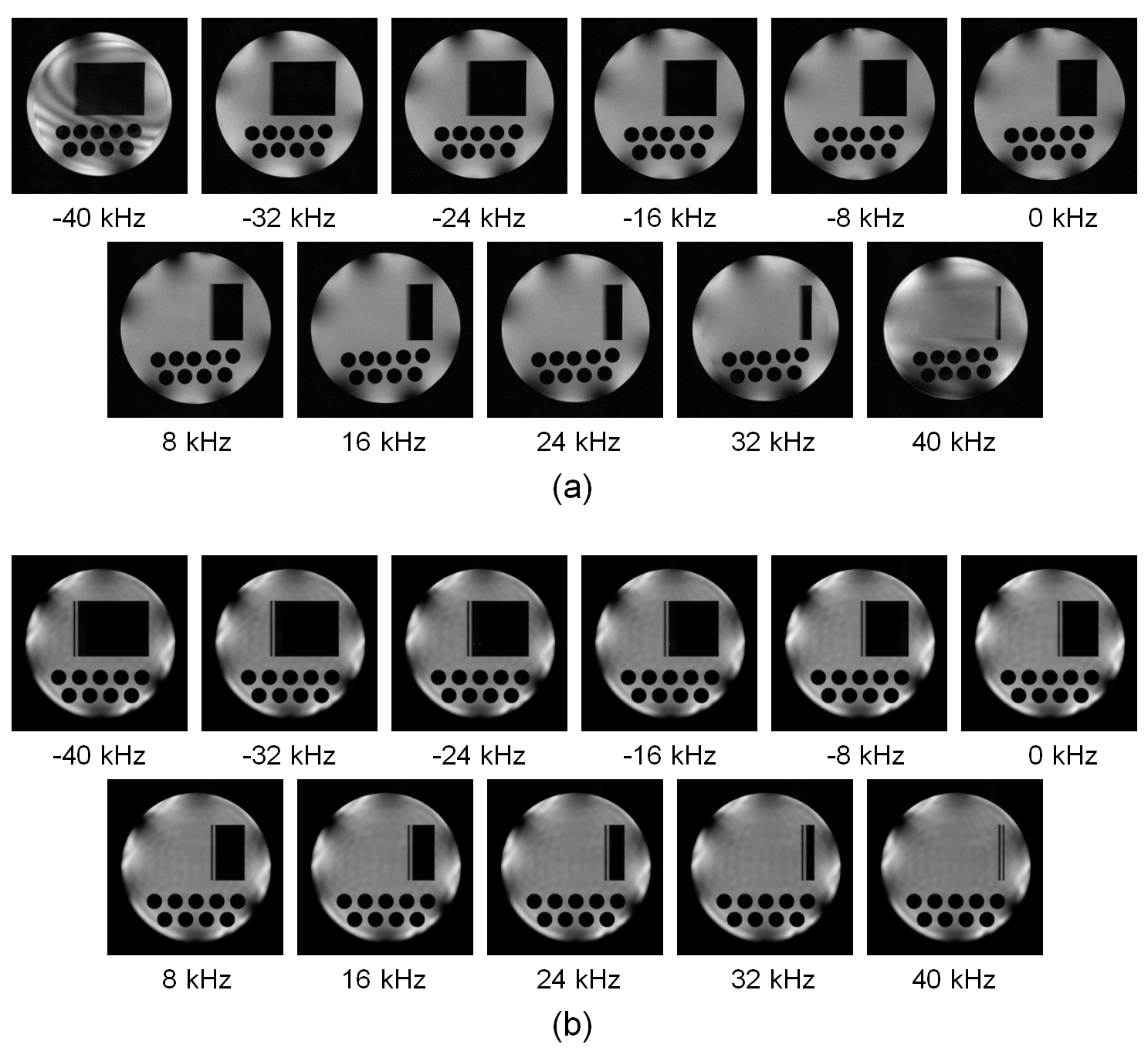
Figure 2 shows the MR signal display window for real-time monitoring the process of the Bloch simulation. Figures 2(a) and (b) show MR signal for a gradient-echo multi-slice sequence and that for a 3D-SPGR sequence. The overhead time for the MR signal display was negligible comparing with the simulation time. Figure 3 shows 2D cross-sectional images acquired with the gradient-echo multi-slice sequence calculated using short pulse approximation of the selective-excitation pulse. The matrix size for the calculation was 256×256×512 with two subvoxels along the readout direction. The number of the short square pulses was 100 and 200 for (a) and (b), and the calculation time was 190 and 472 seconds for (a) and (b). While ghost images were observed when 100 pulses were used, no ghost image was observed when 200 pulses were used. This result clearly demonstrated that the 100 short pulses cannot describe the motion of the magnetization accurately when the offset frequency is more than about ±30 kHz. Figure 4 shows cross-sectional images acquired with the gradient-echo multi-slice sequence when the number of subvoxel was changed from 1 to 8. The matrix size for the calculation was 128×128×512. While considerable artifacts were observed when the number of subvoxel was less than 2, the artifacts disappeared when it was more than 4. Figure 5 shows comparison between (a) experiments and (b) simulation. B1 distribution experimentally measured beforehand was used for RF transmission and signal reception. The B1 distribution was rotated from the experiment to the simulation because the birdcage coil was actually rotated.Discussion
In Bloch simulation, there are two massive calculations: one is summation of magnetization vector over all voxels to acquire MR signal, and the other is calculation of RF excitation in inhomogeneous magnetic fields such as slicing gradients. In our Bloch simulator, the former problem was solved using the parallel processing capability of the GPU and the latter problem was solved using Rodrigues' rotation formula, which simplified several rotation operations to one matrix operation. In the present study, it was found that the number of short square pulses used to approximate the selective excitation pulse and the number of subvoxel to calculate MR images in the imaging plane were very important factors to accelerate the simulation speed. In conclusion, our GPU optimized Bloch simulator has sufficient capability to be applied to multi-slice imaging, which is clinically important and useful.Acknowledgements
This study is supported by Japan Science and Technology Agency.References
[1] Kose R, Kose K, GPU optimized fast 3D MRI simulator, Proc. Intl. Soc. Mag. Reson. Med. 24 (2016) 3202.Figures
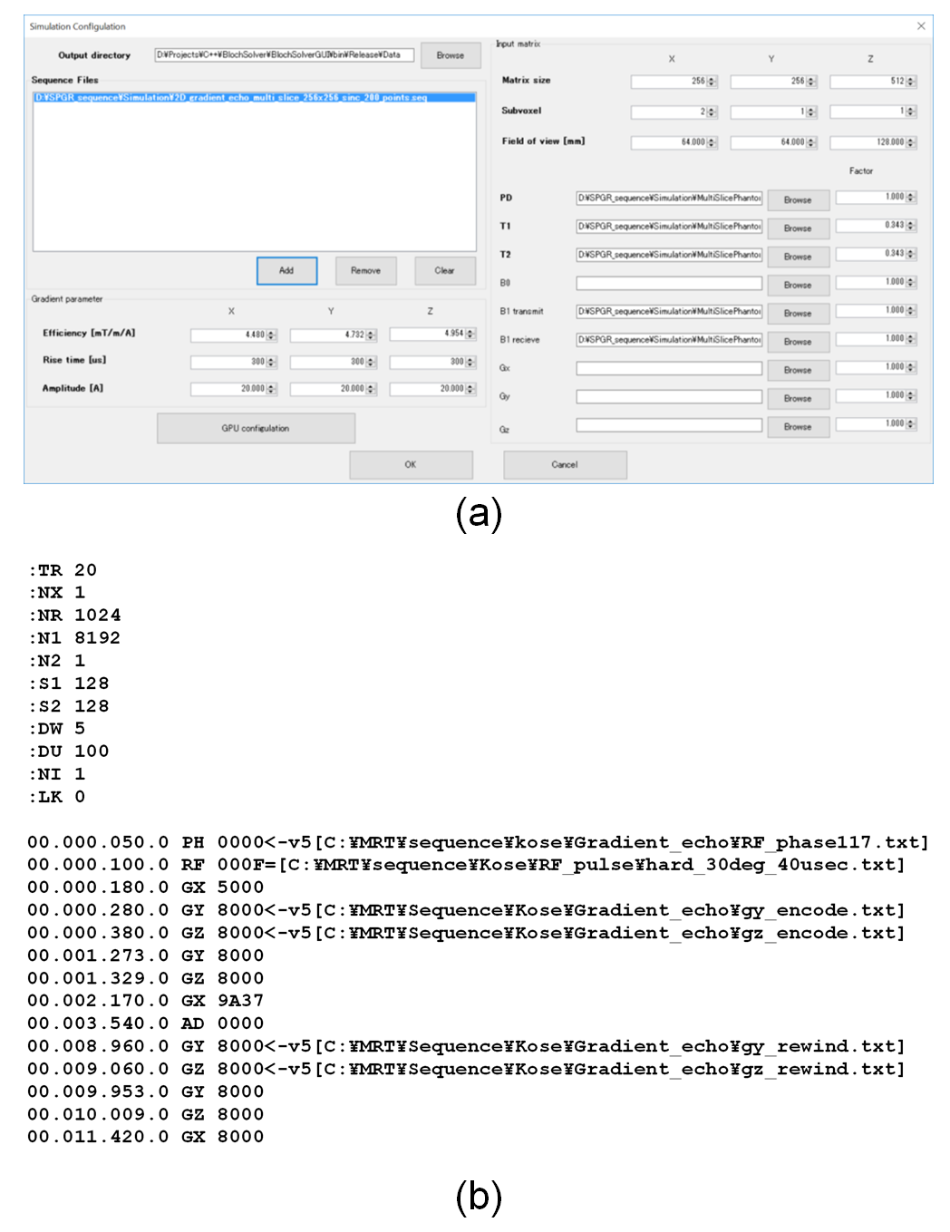
(a) Dialog box for the Bloch simulator developed in this study. (b) A typical
pulse sequence file for a 3D RF spoiled gradient echo sequence that can be used
for both experiments and simulation. The initial part of the sequence file
describes global parameters for the pulse sequence and the latter part is the
time table for the pulse sequence of RF pulses, gradient waveform, and data
acquisition.
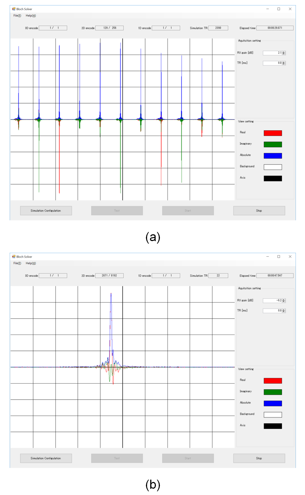
MR signal display window for real-time monitoring the process of the
Bloch simulation. (a) MR signal for a gradient echo multi-slice sequence. 11
echoes for 2D cross-sectional planes are displayed. (b) MR signal for a 3D RF
spoiled gradient echo sequence. The red, green, and blue lines show real
(in-phase), imaginary (quadrature-phase), and absolute value of the MR signal,
respectively.
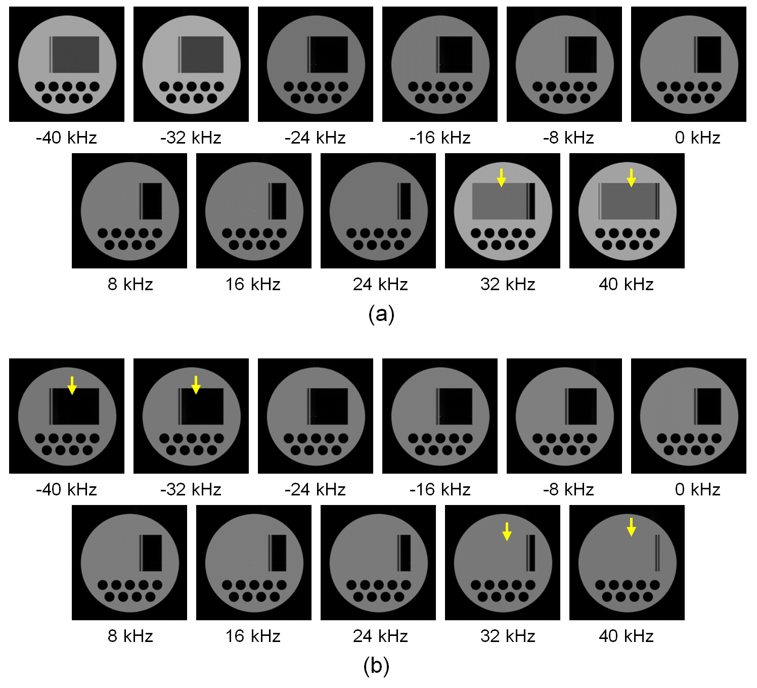
2D cross-sectional images acquired with the gradient-echo multi-slice (11
slice) sequence. TR/TE = 1200ms/6ms and the interval of the RF excitation was
100 ms. T1 and T2 of the numerical phantom was 120 ms. The
in-plane image matrix size was 256×256
and two subvoxels along the readout direction were used for MR signal
calculation. (a) The selective excitation pulse was approximated by 100 short
square pulses. Ghost images are observed as shown by the arrow. (b) The
selective excitation pulse was approximated by 200 short square pulses. Ghost
images disappeared.
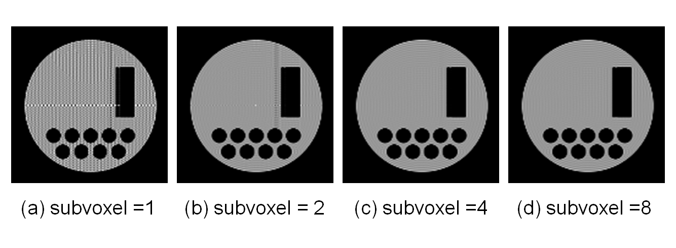
2D cross-sectional images acquired with the gradient-echo multi-slice
sequence. TR/TE = 1200ms/6ms and the interval of the RF excitation was 100 ms.
T1 and T2 of the numerical phantom was 120 ms. The
in-plane image matrix was 128×128
and the number of the subvoxels along the readout direction were changed for MR
signal calculation. The number of subvoxel was (a) 1, (b) 2, (c) 4, and (d) 8.
Comparison
between experiments and simulation. (a) Experiments using a water phantom in a birdcage
coil (diameter = 64 mm, length = 64 mm). (b) Simulation with B1
inhomogeneity. B1 distribution experimentally measured was used for
RF transmission and signal reception. The B1 distribution was
rotated from the experiment to the simulation because the birdcage coil was
actually rotated.