1508
Sequence Design by Signal Inversion Using Extended Phase Graphs1Electrical Engineering, Stanford University, Stanford, CA, United States
Synopsis
In this work, we show that MR signal progression can be represented as an autonomous discrete linear dynamical system when the small angle approximation is made. This formalism can be used to determine an optimal set of flip angles to yield a desired magnetic state. We present an an example of maintaining a constant signal strength with a Fast Spin Echo sequence.
Purpose
We have previously shown that the signal progression of a Fast Spin Echo (FSE) sequence in the Extended Phase Graph domain (EPG) [1]can be represented as a sum of Cellular Automata [2]. This expression can be formed as a recursive function. In this document, we show that (when we make the small tip angle approximation) this recursion is an autonomous discrete linear dynamical system (ADLDS). If an initial condition and a desired end state are specified then the ADLDS can be rewritten as a linear system. This linear system can be solved to determine an optimal set of pulse parameters.Theory
The nominal flip angles of a CPMG FSE sequence are:
\begin{equation} \alpha = \left( 90_x, 180_y, 180_y, 180_y, \ldots, 180_y\right).\end{equation}
Our goal is to determine a vector $$$\Delta\alpha\in\mathbb{R}^M$$$ (where $$$\alpha_j+\Delta\alpha_j$$$ is the angle of the $$$j^{\text{th}}$$$ $$$180_y$$$ pulse) such that the signal is optimally retained throughout a fast spin echo sequence for a given $$$t_1, t_2, T_1, $$$ and $$$T_2$$$. We make the following approximations: $$$\sin(\Delta \alpha_j)\approx\Delta \alpha_j$$$ and $$$\cos(\Delta \alpha_j)\approx 1$$$ for all $$$j$$$. The matrix representing a $$$\alpha + \Delta\alpha_y$$$ RF pulse becomes
\begin{equation*} R_{\alpha+\Delta\alpha}\left(\begin{bmatrix}F_n^+\\F_n^-\\Z_n\end{bmatrix}\right) \approx R_{\alpha} \begin{bmatrix} F_n^+ + \Delta\alpha \, Z_n \\ F_n^- + \Delta \alpha \, Z_n \\ -\Delta\alpha/2 \left(F_n^++F_n^-\right) + Z_n \end{bmatrix} = R_{\alpha}\begin{bmatrix}F_n^+\\F_n^-\\Z_n\end{bmatrix} + \Delta\alpha \, R_{\alpha}\begin{bmatrix}Z_n\\Z_n\\-(F_n^++F_n^-)/2\end{bmatrix}.\end{equation*}
As detailed in [2], the EPG states can be represented as
\begin{equation} Q_m(n) = C_{Q_0}(m,n) + \sum_{i=1}^m C_{\tilde{Q}}(m-i,n), \label{eq:totalSignal}\end{equation}
where $$$Q_m$$$ is a vector of the coefficients at time $$$m>1$$$, $$$\tilde{Q}$$$ is the magnetization due to recovery after a single TR, and $$$Q_0$$$ is the magnetic state at the echo after the $$$90_x$$$ pulse (when $$$m=0$$$). The value $$$C_Q(m,\cdot)$$$ is defined as
\begin{align} C_{Q}(m+1,n) &= \underbrace{\begin{bmatrix} e^{-t_2/T2} R_{\alpha_m,1}^T \left(e^{-t_1/T2} F_{n-2}^+,e^{-t_1/T2}F_n^-,e^{-t_1/T1} Z_{n-1}\right) \\ e^{-t_2/T2} R_{\alpha_m,2}^T \left(e^{-t_1/T2} F_{n}^+,e^{-t_1/T2}F_{n+2}^-,e^{-t_1/T1} Z_{n+1}\right) \\ e^{-t_2/T1} R_{\alpha_m,3}^T \left(e^{-t_1/T2} F_{n-1}^+, e^{-t_1/T2}F_{n+1}^-, e^{-t_1/T1} Z_n\right) \end{bmatrix} }_{A \, C_Q(m-1,n)} \nonumber \\ &+ \underbrace{\begin{bmatrix}e^{-t_2/T2} R_{\alpha_m,1}^T \left(e^{-t_1/T1}Z_{n-1}, e^{-t_1/T1}Z_{n-1}, -e^{-t_1/T2}(F_{n-2}^++F_n^-)/2\right) \\ e^{-t_2/T2} R_{\alpha_m,2}^T \left(e^{-t_1/T1}Z_{n+1}, e^{-t_1/T1}Z_{n+1}, -e^{-t_1/T2}(F_n^++F_{n+2})/2\right) \\ e^{-t_2/T1} R_{\alpha_m,3}^T \left(e^{-t_1/T1}Z_n, e^{-t_1/T1}Z_n, -e^{-t_1/T2}(F_{n-1}^++F_{n+1}^-)/2\right) \end{bmatrix} }_{B \, C_Q(m-1,n)} \Delta\alpha_m,\end{align}
where $$$Q$$$ represents the initial condition $$$(C_{Q}(0,n)=Q)$$$, $$$R_{\alpha,j}^T$$$ represents the $$$j^{\text{th}}$$$ row of $$$R_{\alpha}$$$, and $$$\cdot^T$$$ represents transpose. The equation above is an ADLDS. Since $$$Q_m$$$ is a sum of $$$C$$$ functions, it too is an ADLDS. At some final time $$$M$$$,
\begin{align}C_Q(M,\cdot) =& \hspace{4pt} A^M C_Q(0,\cdot) + A^{M-1} B C_Q(0,\cdot) (\alpha_1+\Delta\alpha_1) + A^{M-2} B A C_Q(0,\cdot) (\alpha_2\Delta\alpha_2) \nonumber \\ &+ A^{M-3} B A^2 C_Q(0,\cdot) (\alpha_3+\Delta\alpha_3) + \cdots \nonumber \\ &+ ABA^{M-2} C_Q(0,\cdot) (\alpha_{M-1}+\Delta\alpha_{M-1}) + B A^{M-1} C_Q(0,\cdot) (\alpha_M+\Delta\alpha_M).\end{align}
where $$$\alpha_i \alpha_j\, \approx 0$$$ for any $$$i,j$$$. Combining the above equations,
\begin{align}\underbrace{\boldsymbol{1}^T\begin{bmatrix}A^{M-1}BQ_0&A^{M-2}BAQ_0&A^{M-3}BA^2Q_0&\cdots&BA^{M-1}Q_0\\ & A^{M-2}B\tilde{Q} & A^{M-3}BA\tilde{Q} & & BA^{M-2}\tilde{Q} \\ & & A^{M-3}B\tilde{Q} & & BA^{M-3}\tilde{Q} \\ & & & \ddots & \vdots \\ & & & & B\tilde{Q} \end{bmatrix}}_{\boldsymbol{H}}\begin{bmatrix}I\Delta\alpha_1\\ I\Delta\alpha_2 \\ I \Delta\alpha_3 \\ \vdots \\ I \Delta\alpha_M \end{bmatrix} = \nonumber \\ \underbrace{ Q_D - \boldsymbol{1}^T \begin{bmatrix} A^M Q_0 - A^{M-1} B Q_0 \alpha_1 - A^{M-2} B A Q_0 \alpha_2 - \cdots - B A^{M-1} Q_0 \alpha_M \\ A^{M-1} \tilde{Q} - A^{M-2} B \tilde{Q} \alpha_2 - \cdots - B A^{M-2} \tilde{Q} \alpha_M \\ A^{M-2} \tilde{Q} - \cdots - B A^{M-3} \tilde{Q} \alpha_M \\ \vdots \\ A \tilde{Q} - B \tilde{Q} \alpha_M \end{bmatrix} }_{\boldsymbol{b}}\end{align}
where $$$\boldsymbol{1}$$$ is a block vector with all values equal to $$$I$$$, and $$$Q_D$$$ is a variable specifying the desired state. One can solve the following constrained least squares problem to find an optimal $$$\alpha$$$ that attains a specific desired end state $$$Q_D$$$:
\begin{align*} \text{minimize} & \hspace{8pt} \| \boldsymbol{H} \alpha - \boldsymbol{b} \|_2 \\ \text{subject to} & \hspace{8pt} |\alpha| \leq \theta,\end{align*}
where $$$\theta$$$ is a small angle (e.g. $$$pi/2$$$, imposed so that the small angle approximation remains valid).
Results
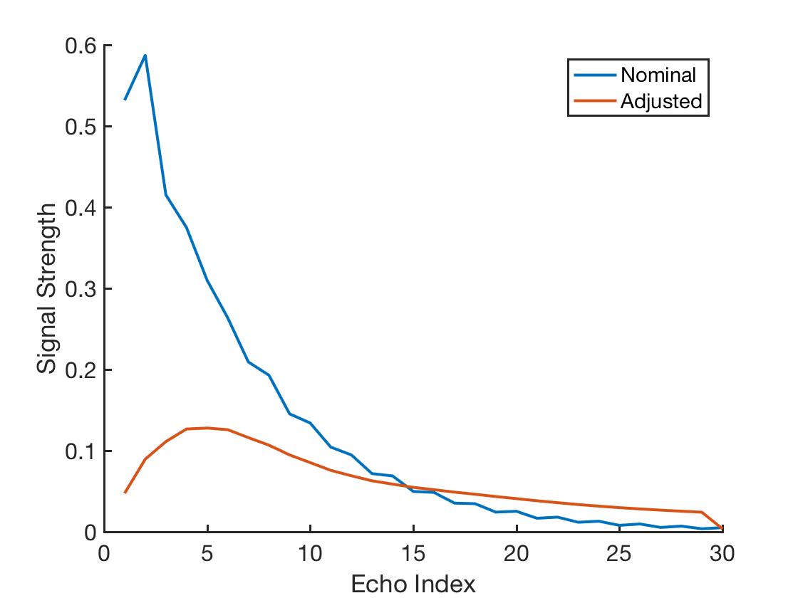
We use this formalism to determine an optimal $$$\Delta\alpha$$$ that maintains a maximum signal strength through $J=30$ echoes of a fast spin echo sequence. Let $$$\boldsymbol{H}_j$$$ be the matrix $$$\boldsymbol{H}$$$ associated with the $$$j^{\text{th}}$$$ echo. Then the optimal $$$\Delta\alpha$$$ is determined by solving the following optimization problem:
\begin{align*} \text{minimize} & \hspace{8pt} \| \boldsymbol{H}_1 \alpha_{1} - \boldsymbol{b}_1 \|_{\mathbb{I}_{F_0^+},2} + \| \boldsymbol{H}_2 \alpha_{1:2} - \boldsymbol{b}_{1:2} \|_{\mathbb{I}_{F_0^+},2} + \cdots + \| \boldsymbol{H}_J \alpha_{1:J} - \boldsymbol{b}_{1:J} \|_{\mathbb{I}_{F_0^+},2} \\ \text{subject to} & \hspace{8pt} |\Delta\alpha| < \theta,\end{align*}
where each term in the objective function is a norm weighted by the indicator function of the $$$F_0^+$$$ element. This problem can be solved with the Fast Iterative Shrinkage Threshold Algorithm (FISTA) [3] or interior point methods.
Figure 1 compares the simulated signal strength for the nominal FSE CPMG sequence with 20 ms echo spacing to that using the altered flip angles. For this result, the desired signal strength was set to $$$1$$$ for all echoes. The signal strength is retained for many more echoes.
Discussion
This approach can be generalized to other sequences (not just FSE), which we will do as future work.Acknowledgements
ND is supported by the National Institute of Health's Grant Number T32EB009653 “Predoctoral Training in Biomedical Imaging at Stanford University”, the National Institute of Health's Grant Number NIH T32 HL007846, The Rose Hills Foundation Graduate Engineering Fellowship, the Electrical Engineering Department New Projects Graduate Fellowship, and The Oswald G. Villard Jr. Engineering Fellowship
References
[1] Matthias Weigel. Extended Phase Graphs: Dephasing, RF pulses, and Echoes - Pure and Simple. Journal of Magnetic Resonance Imaging, 41(2):266–295, 2015.
[2] Nicholas Dwork, Brian A. Hargreaves, and John M. Pauly. Using Cellular Automata to Represent MRI Signal Progression. In Proceedings of the International Society of Magnetic Resonance in Medicine, 2016.
[3] Amir Beck and Marc Teboulle. A Fast Iterative Shrinkage-thresholding Algorithm for Linear Inverse Problems. SIAM journal on imaging sciences, 2(1):183–202, 2009.
Figures