1493
An algorithm for refocusing of T2* effects in bSSFP-MRF with relaxation corrections1Physics, Case Western Reserve University, Cleveland, OH, United States, 2Biomedical Engineering, Case Western Reserve University, Cleveland, OH, United States, 3Radiology, University Hospitals Case Medical Center, Cleveland, OH, United States
Synopsis
It is found that bSSFP-MRF is in general subject to T2* not T2 relaxation. Like traditional bSSFP, dephasing effects of intra-voxel inhomogeneities can be refocused in bSSFP-MRF with appropriate choices in TR, TE, and FA so that parameter maps are reflective of T2 rather than T2*. An algorithm is introduced and verified in simulation for refocusing intra-voxel dephasing at TE for bSSFP-MRF with corrections to previous work for relaxation effects previously assumed as negligible. These corrections are relevant for bSSFP-MRF in which T2 is not much larger than TR to ensure that T2 maps do not contain T2* effects.
Purpose
To introduce a means of refocusing local dephasing due to T2* effects in bSSFP-MRF taking into account T2 relaxation effects. In the presence of varying susceptibilities and field inhomogeneities, it has been shown that bSSFP-based MRF is subject to T2*, rather than T2, relaxation effects, which can result in an underestimation within T2 maps [1]. A refocusing method has previously been presented to correct for T2* dephasing neglecting intrinsic relaxation effects [1]. In certain imaging experiments, however, T2 may not be much larger than chosen TR and TE values. Therefore, in this work we consider finite relaxation times to present analytic corrections to the previous work for choices of FA, TE and TR that generate rephasing of T2* effects at time TE within each repetition of a bSSFP-MRF.Methods
There are two main requirements to produce intra-voxel refocusing at each repetition (time step) in a bSSFP-MRF experiment. First, the FA must be designed so that the polar angle between the z-axis and the magnetization vector alternates in sign every step. This ensures that there is a time within each TR when the accumulated phase of each spin is zero. Then for a magnetization vector at some polar angle $$$ \theta_{i^{-}}$$$ just prior to the ith step, the flip angle $$$ \alpha_{i}$$$ must be chosen so that $$\mid\theta_{i^{-}}\mid\lt\mid\alpha_{i}\mid\lt\mid\theta_{i^{-}}\mid+\pi\tag{1}$$
Second, TR and TE are chosen at each step so, in the limit of small off-resonance and T1>TR, all spins within a voxel have zero phase at TE. To achieve this, we demand Mx=0 at TE in each step. The polar angle at TEi can be found from $$\tan\theta_{i}=\frac{M_{y,i}}{M_{z,i}}=\frac{e^{-TE_{i}/T2}\left(\cos\theta_{i-1}\sin\alpha_i+e^{\left(TE_{i-1}-TR_{i-1}\right)/T2}\cos\alpha_{i}\sin\theta_{i-1}\right)}{\cos\alpha_{i}\cos\theta_{i-1}-e^{\left(TE_{i-1}-TR_{i-1}\right)/T2}\sin\alpha_{i}\sin{\theta_{i-1}}}\tag{2}$$ Then, demanding Mxi=0 gives $$TE_{i}=\frac{e^{TE_{i-1}/T2}\left(TE_{i-1}-TR_{i-1}\right)\sin\theta_{i-1}}{e^{TR_{i-1}/T2}\cos\theta_{i-1}\sin\alpha_{i}+e^{TE_{i-1}/T2}\cos\alpha_{i}\sin\theta_{i-1}}\tag{3}$$ so that each new TE is found in terms of the previous TE and TR. Then TR is a free parameter, which, in keeping with [1], is chosen such that TRi-1 =(TR_SSFP/2)+TEi-1. In this analysis, TR_SSFP is fixed at 15ms. Additionally, the explicit dependence on T2 exhibits the desired generalization in the limit T2 >> TR, equation (3) yields the simpler formula found in [1].
The ability of equations (1), (2), and (3) to determine the refocusing of T2* effects was tested in MATLAB and compared to refocusing at TE for both the FA introduced in [2] with a constant TR=TR_SSFP and TE=TR_SSFP/2, and FA, TE, and TR distributions based on information introduced in [1]. In all three cases, dephasing within each time step was simulated assuming an experimentally reasonable intra-voxel 3 Hz off-resonance frequency spread for TR_SSFP=15ms.
Results
Figure 1 compares three flip angle distributions: FA1 introduced in [2] and used as a standard, FA2 calculated using theory introduced in [1] and appropriate for refocusing, and FA3 calculated by employing equations (1), (2), and (3) and appropriate for refocusing with relaxation corrections.
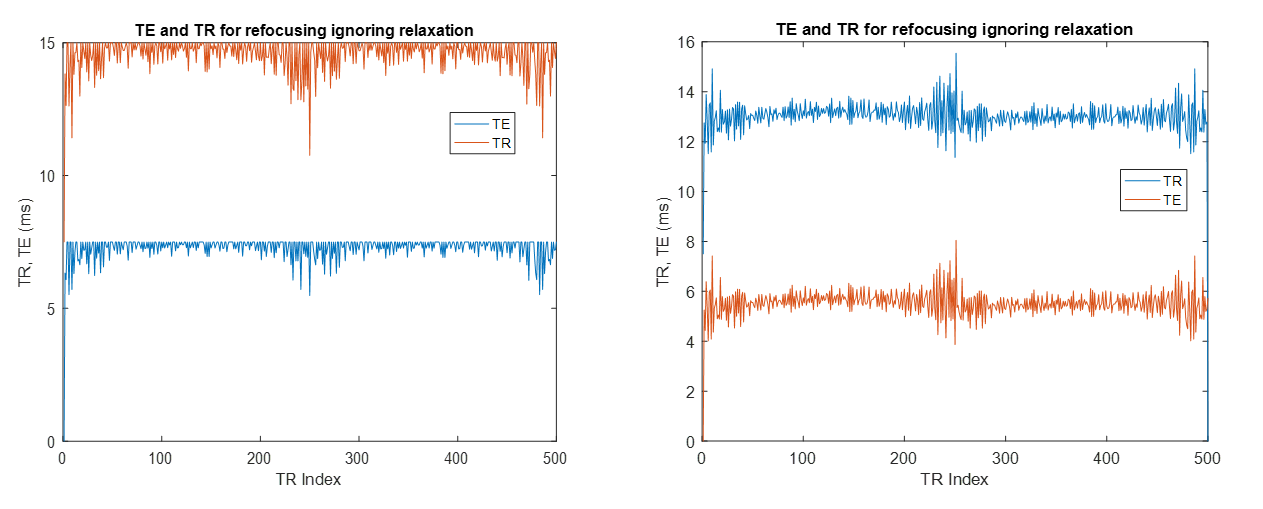
Figure 2 compares the TE and TR distributions calculated to generate refocusing with and without relaxation corrections.
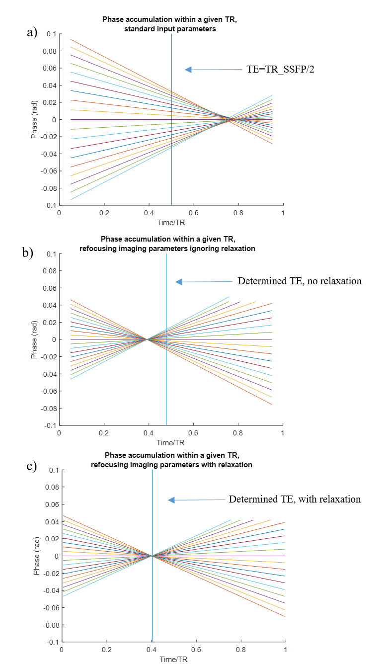
We note initial simulations were used to reproduce the results of [1], where refocusing occurs at determined TE for infinite relaxation times, in contrast to the lack of global refocusing within a given repetition using the FA introduced in [2] and a constant TR distribution. As seen in figure 3b), simulations were then used to show that in the case of T2 on the order of TR and T1>TR (TR_SSFP=15ms, T1=1000ms, T2=40ms), the predicted TE based on [1], was shifted from the actual time of refocusing. To produce figure 3c), equations (1), (2), and (3) were used to calculate appropriate FA, TE, and TR distributions to refocus T2* dephasing effects at time TE. In this case, TR_SSFP=15ms, T1=1000ms, T2=40ms were again used and the accumulation of phase is plotted within a sample time step. Here it is seen that the refocusing does occur at the predicted TE. While the plots in figure 3 show phase accumulation during a particular time step (TR Index=16), the plots chosen are representative of overall trends for all N time steps.
Discussion and Conclusion
The simulated results show an improved ability to refocus intra-voxel dephasing and determine echo time in bSSFP-based MRF by taking into account relaxation effects. This will result in an improved ability to match to T2 rather than T2* when generating parameter maps, particularly in the case that T2 is on the order of TR. The clinical relevance stems from the improvement in the accuracy with which T2 is measured demonstrated in Ref.[1]. For future experiments in which smaller T2 values are important the present results promise an effective generalization of this refocusing method.Acknowledgements
NIH T32EB007509. OTF IPP TECG20140138.References
[1] Assländer J, et al. MRM, doi:10.1002/mrm.26202. [2] Ma D, et al. Nature 495, 187-92 (2013).Figures
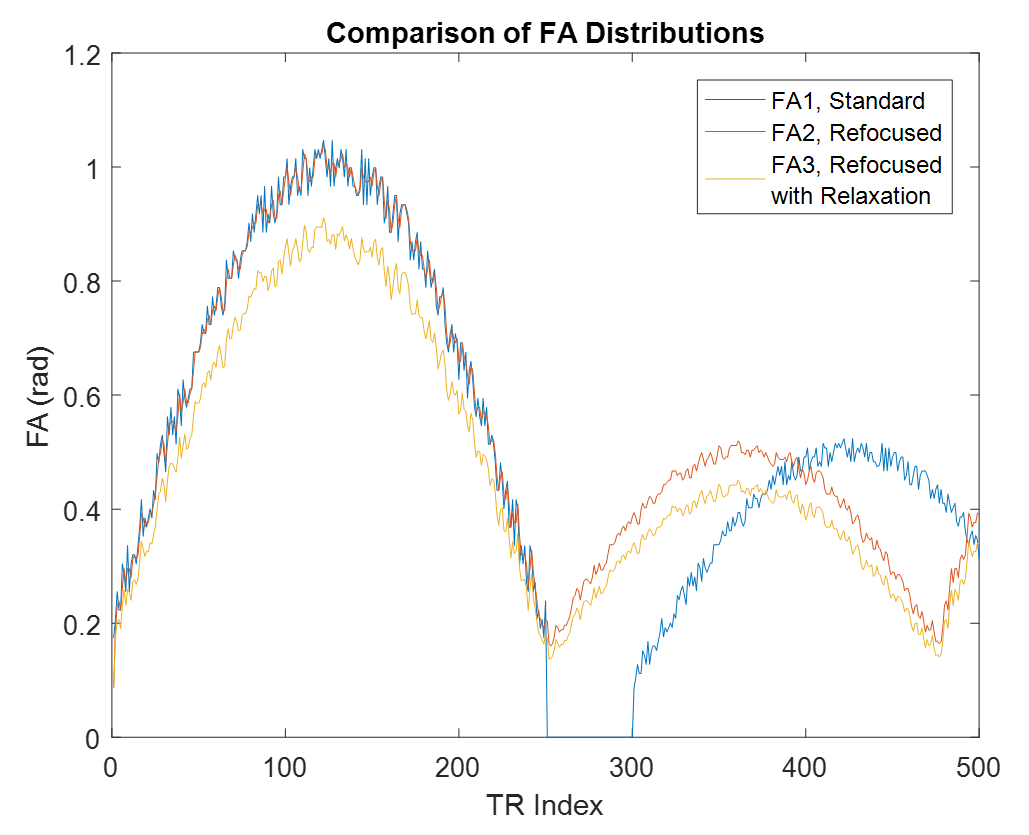
Figure 1: Comparison of 3 flip angle distributions: FA1 - no effort in refocusing, FA2 - for refocusing assuming infinite relaxation times, and FA3 - for refocusing with T2 corrections