1484
SPAMM Based Dual Current Injection to Accelerate Data Acquisition in Magnetic Resonance Electrical Impedance Tomography1Electrical and Electronics Engineering, Middle East Technical University, Ankara, Turkey
Synopsis
Reducing acquisition time in magnetic resonance electrical impedance tomography (MREIT) improves signal to noise ratio and temporal resolution of measured conductivity data. On the other hand, the reconstruction accuracy of MREIT can be improved by acquiring multiple data using different current injection patterns, which in turn increases the total scan time. In this study, a novel pulse sequence is proposed to reduce the scan time in MREIT by injecting two current patterns in a single acquisition. This method is experimentally realized using a physical phantom, and its feasibility is evaluated.
Purpose
Magnetic Resonance Electrical Impedance
Tomography (MREIT) is an MRI-based imaging technique used to image electrical
conductivity distribution inside a volume conductor. In MREIT, electric current is applied to the volume
conductor in synchrony with an MR pulse sequence. Phase image is reconstructed
utilizing the acquired data. Current distribution inside the volume reflects
the conductivity distribution in the volume. This conductivity information can
be recovered from magnetic flux density induced by the applied current. The
magnetic flux density distribution can be extracted from reconstructed MR phase
image. Acquiring magnetic flux density using different current injection
patterns helps in recognizing more details about the unknown conductivity
distribution1, which is useful for reconstructing anisotropic or
complex-structured conductivity. This however, increases the total time needed for
data acquisition. In this study, a new method based on spatial modulation of
magnetization (SPAMM) is proposed. In this method, applying two independent
current patterns at the same acquisition time reduces MREIT scan time by half.Methods
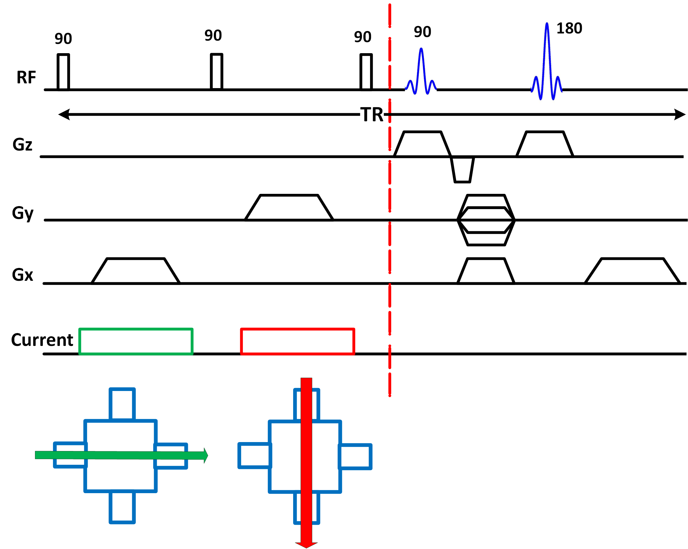
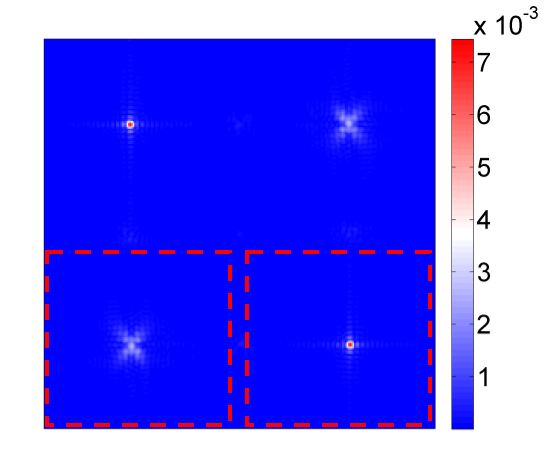
Recently, Sümser et al. proposed injecting current during a preparation module prior to the beginning of actual imaging pulse sequence2. This concept is adopted in this study to inject two different current patterns at the same pulse repetition (TR) period, as illustrated in Figure 1. The first current injection pattern is assumed to be applied horizontally between the left and the right electrodes, and the second pattern to be applied vertically between the top and the bottom electrodes. Utilizing this pulse sequence, the k-space data shown in Figure 2 is acquired. The k-space data is composed of four signal replicas that can be windowed and transformed to spatial domain independently. Each two signal replicas centered on the same diagonal line have the same phase information but with opposite sign. Therefore, two signal replicas are sufficient to recover current-related phase data. Phases of the bottom pair of signal replicas can be related analytically to the phases introduced by current injections as:
$$\phi_{L} = \phi_{H} + \phi_{V}\quad\quad\quad(1)$$
$$\phi_{R} = \phi_{H} - \phi_{V}\quad\quad\quad(2)$$
where $$$\phi_{L}$$$ and $$$\phi_{R}$$$ are the phase images recovered from the left and the right signal replicas respectively, and $$$\phi_{H}$$$ and $$$\phi_{V}$$$ are the phase terms introduced by the horizontal and the vertical current injections respectively. These two equations imply that current-related phase images can be recovered as:
$$ \phi_{H} = \frac{ \phi_{L} + \phi_{R}}{2}\quad\quad\quad(3)$$
$$ \phi_{V} = \frac{ \phi_{L} - \phi_{R}}{2}\quad\quad\quad(4)$$
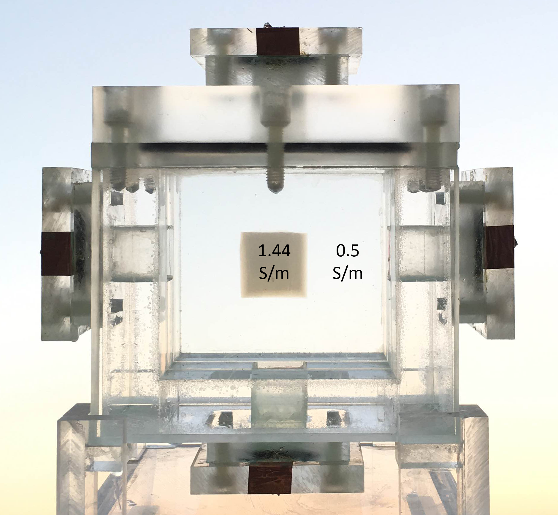
The proposed method is tested experimentally using a 3T Siemens scanner at National Magnetic Resonance Research Center (UMRAM), the physical phantom shown in Figure 3, and a multi-channel MR-compatible current source3. The phantom has a cavity of 8×8×8cm3 dimensions filled with a saline solution of 0.5S/m conductivity. A cube-shaped Agarose object of 2.5cm side-length and 1.44S/m conductivity is placed at the center of the cavity to introduce a conductivity inhomogeneity. Current pulse of 20mA amplitude and 15ms duration is applied horizontally within the duration between the 1st and the 2nd 90o RF pulses, and then vertically between the 2nd and the 3rd 90o RF pulses. Imaging parameters used to collect data are: FOV/pixels = 256mm/256, TE/TR= 17ms/500ms, slice thickness = 5mm and number of averaging = 4. Conductivity images within imaging slice is reconstructed by using Sensitivity Matrix Method (SMM)1.
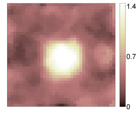
Results
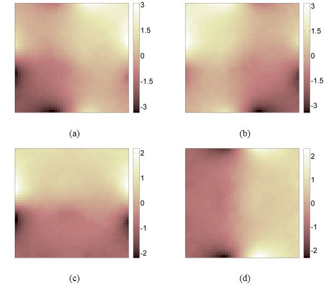
Recovered phase images from the bottom pair of signal replicas are shown in Figure 4a and Figure 4b, respectively. $$$\phi_{H}$$$ and $$$\phi_{V}$$$ recovered using (3) and (4) are shown in Figure 4c and Figure 4d, respectively. These two phase images are then scaled to the corresponding magnetic flux density data that are used for conductivity reconstruction. Reconstructed conductivity distribution using SMM is shown in Figure 5. Reconstruction accuracy is evaluated using root-mean-square error, which is found to be 10% and 17% in the object and the background regions respectively.
Conclusion
In this study, a new acquisition method is proposed to reduce scan time in MREIT. This method was realized using phantom experiment, and the obtained results demonstrated the validity of the proposed concept to reduce the scan time by a factor of two. Short scan time is desirable in 3D conductivity imaging, to avoid motion artifacts and to minimize patient discomfort. To take full advantage of the proposed method, it is planned to implement its concept on a single-shot pulse sequence to further reduce acquisition time.Acknowledgements
This research is funded by METU Research grant BAP-07-02-2014-007- 470. N Naji and K Sümser are research students supported by Turkish Scientific and Technological Research Council grant 113E979. MREIT current source used in the experiments is designed and implemented by Hasan H. Eroglu.References
1. Ider YZ, Birgül Ö. Use of the magnetic field generated by the internal distribution of injected currents for electrical impedance tomography (MR-EIT). Turkish Journal of Electrical Engineering & Computer Sciences. 2000; 6(3):215-226.
2. Sümser K, Naji N, Sadighi M, et al. MRI-SPAMM Based Magnetic Resonance Electrical Impedance Tomography. Proceedings of the 24th Annual Meeting of ISMRM. 2016;1940.
3. Eroglu HH, Eyüboglu BM, Göksu C. Design and implementation of a bipolar current source for MREIT applications. In 13th Mediterranean Conference on Medical and Biological Engineering and Computing. 2013; 161–164.
Figures