1482
Intra-Scan Center Frequency Drift Correction for 3D Spiral Exams1Magnetic Resonance Technology Design Group, Barrow Neurological Institute, Phoenix, AZ, United States, 2Philips Healthcare, Cleveland, OH, United States
Synopsis
High gradient demand and heating results in a changing main magnetic field and center frequency drift during minutes-long acquisitions. Center frequency drifts on the order of tens of Hz may produce visible artifacts in images acquired with long-readout spiral acquisitions. We propose a method for removing such artifacts in spiral acquisitions by demodulating individual spiral arms using a linear interpolation of center frequency measured before and after a scan.
Purpose
To correct artifacts caused by intra-scan center frequency drift.Introduction
Spiral trajectories with long readout times may be used to optimize scan efficiency. Unfortunately, longer readouts increase sensitivity to off-resonance such as chemical shift and main field inhomogeneity ($$$\Delta B_0$$$). These effects may be corrected using Dixon-based water-fat separation and deblurring [1] with an a priori measured $$$\Delta B_0$$$ map so long as they remain static during the acquisition.
High gradient demand in spiral acquisitions results in substantial power dissipation through gradient heating. While the gradient coil itself is water-cooled, many other components in the scanner (e.g. the passive shims) may retain heat. As previously shown, this heating is correlated with $$$\Delta B_0$$$ changes [2]. Although efficient trajectories reduce scan times, high resolution 3D scans may still take several minutes. This is long enough to observe center frequency ($$$f_0$$$) drifts on the order of tens of Hz, which can produce visible artifacts in the image.
Methods
Constant changes in $$$B_0$$$ can be compensated by measuring and resetting $$$f_0$$$ before each scan. To compensate for intra-scan drift, however, we linearly interpolate between $$$f_0$$$ measurements before and after each scan. Each spiral arm is then demodulated with respect to the estimated $$$\Delta f_0$$$:
$$D_n = D_n e^{(-j 2\pi t ((1-\frac{n}{N})\Delta f_{0,start} + \frac{n}{N} \Delta f_{0,end}))}$$
where $$$D_n$$$ is the k-space data for each spiral arm, $$$n$$$ is the spiral arm acquisition index, and $$$N$$$ is the total number of spiral arms.
Phantom and volunteer data were acquired at 3T on a Philips Ingenia scanner (Philips Healthcare, Best, The Netherlands). The spiral trajectory was a hybrid 3D stack-of-spirals, with an ADC time $$$\tau = 15 ms$$$ for the phantom scans, and $$$\tau = 10 ms$$$ for the volunteer scan.
Results and Discussion
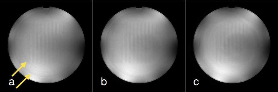
Figure 1 illustrates the intra-scan $$$f_0$$$ drift artifact in a large cylindrical phantom, along with two examples for mitigating or correcting the artifact. Figures 1a and 1b show the same data, collected with linear arm ordering (linearly increasing spiral arm angle from $$$0$$$ to $$$2\pi$$$), with z-encoding (phase encoding) as the inner loop. Figure 1c is from a second scan acquired with mixed arm ordering [3] with z-encoding as the outer loop. The drift artifact in question appears as dark rings in the phantom, indicated by the arrows in Figure 1a. The artifact is reduced as shown in Figure 1b by the post-acquisition demodulation described above. Figure 1c shows the artifact can also be mitigated by re-ordering the acquisition. Intra-scan $$$f_0$$$ drift for all phantom scans was 8 Hz over approximately 2 minutes.
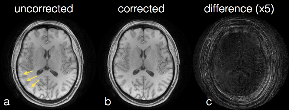
Figure 2 shows the intra-scan $$$f_0$$$ drift artifact for a volunteer. The image in Figure 2a was acquired using (as in Figure 1a and 1b) linear arm ordering with z-encoding as the inner loop. The artifact indicated by the arrows in Figure 2a is effectively eliminated by the demodulation technique described above, as shown in Figure 2b. The amplified difference image in Figure 2c indicates areas where the artifact was removed. Intra-scan $$$f_0$$$ drift for this volunteer scan was 16 Hz over approximately 3 minutes.
We have demonstrated effective methods for removing (via demodulation) or mitigating (via robust arm ordering) artifacts from k-space inconsistency created by intra-scan drift of $$$f_0$$$, likely caused by scanner heating. Using demodulation to correct the artifact is generally preferable, as reordering the acquisition may change or enhance the appearance of other artifacts such as those caused by flow or pulsation. Our observations indicate that heating primarily results in changes to the center frequency [2], but additional artifacts from spatially varying changes to the magnetic field may remain.
Acknowledgements
This research was funded in part by a grant from Philips Healthcare.
Some data for this work was acquired in a collaboration with Phoenix Children's Hospital.
References
[1] Wang, D., Zwart, N. R., Li, Z., Schär, M., & Pipe, J. G. (2016). Analytical three-point Dixon method: With applications for spiral water-fat imaging. Magnetic Resonance in Medicine, 75(2), 627–638.
[2] Ooi, M. B., Wang, D., Li, Z., Zwart, N. R., Robison, R. K., & Pipe, J. G. (2016). Spiral Deblurring Using B0 Maps with B0 Drift Correction. In 24th Annual Meeting of ISMRM (p. 1760). Singapore.
[3] Pipe, J. G., Ahunbay, E., & Menon, P. (1999). Effects of interleaf order for spiral MRI of dynamic processes. Magnetic Resonance in Medicine, 41(2), 417–422.
Figures