1481
Three-dimensional T1-weighted spiral imaging of the spine1Imaging Research, Barrow Neurological Institute, Phoenix, AZ, United States, 2Philips Healthcare, United States
Synopsis
Spine imaging requires lengthy examination times to yield sufficient SNR and to account for patient motion. Spiral MRI is a promising method for yielding high SNR acquisitions with reduced scan times and is more robust to patient motion. This work investigates the feasibility of applying spiral MRI to T1w imaging of the spine. Initial results indicate that spiral is well suited for anatomical spine imaging.
Purpose
To evaluate T1-weighted spiral MRI in the spine.Introduction
Spine MRI exams often require the patient, who may be suffering from back pain or other discomfort, to lie on the bed and hold still for long periods of time. Long scan times are necessitated in part by SNR requirements and patient motion issues. Spiral MRI is a promising method for obtaining high SNR in short scan times while mitigating some of the effects of patient motion. Spiral has been used in the brain to obtain image quality comparable to that obtained using standard Cartesian acquisitions while requiring shorter scan times [1-4]. In these studies, spiral MRI yielded equivalent or better SNR and was more robust to flow related artifacts. Spiral has been previously used in the spine for DTI [5], T1ρ [6], and fMRI [7] acquisitions. The current work investigates gradient echo spiral MRI in sagittal T1 imaging of the spine. To our knowledge, spiral MRI has not yet been studied in T1 weighted imaging of the spine.
Methods
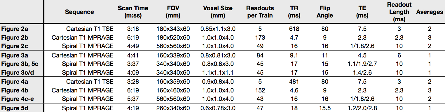
Cervical, thoracic, and lumbar spine data were acquired on a 3.0T Ingenia (Philips Healthcare, Best, Netherlands) using 2D Cartesian T1w TSE, 3D Cartesian T1w MPRAGE, and 3D spiral T1w MPRAGE sequences. Sequence parameters corresponding to all image data are provided in table 1. Spiral images were compared to the corresponding Cartesian images to evaluate artifacts, off-resonance blurring, and motion on the overall image quality.
Gradient echo T1w sequences were selected for testing the feasibility of T1w spiral MRI in the spine. It was observed that T1w MPRAGE provided better CSF suppression and cord delineation compared to similar T1w gradient echo acquisitions. T1w MPRAGE has also been shown to provide good lesion conspicuity in MS patients [8]. Spiral data were acquired at multiple echo times, which allowed for mDixon fat/water separation. Separate B0 maps were acquired for use in deblurring. The acquired FOV for all MPRAGE scans was expanded in the superior/inferior (SI) direction to avoid foldover artifacts. All images were cropped to show only the desired FOV.
The spiral design typically requires a circular FOV. However, it is possible to achieve an elliptical FOV simply by reducing the gradient amplitude in the SI direction by a factor f. This will cause the supported FOV to be larger by a factor of f in that direction. The voxel size will also increase by the same factor of f in the SI direction. Example elliptical FOV spiral data were acquired in the cervical spine.
Results and Discussion
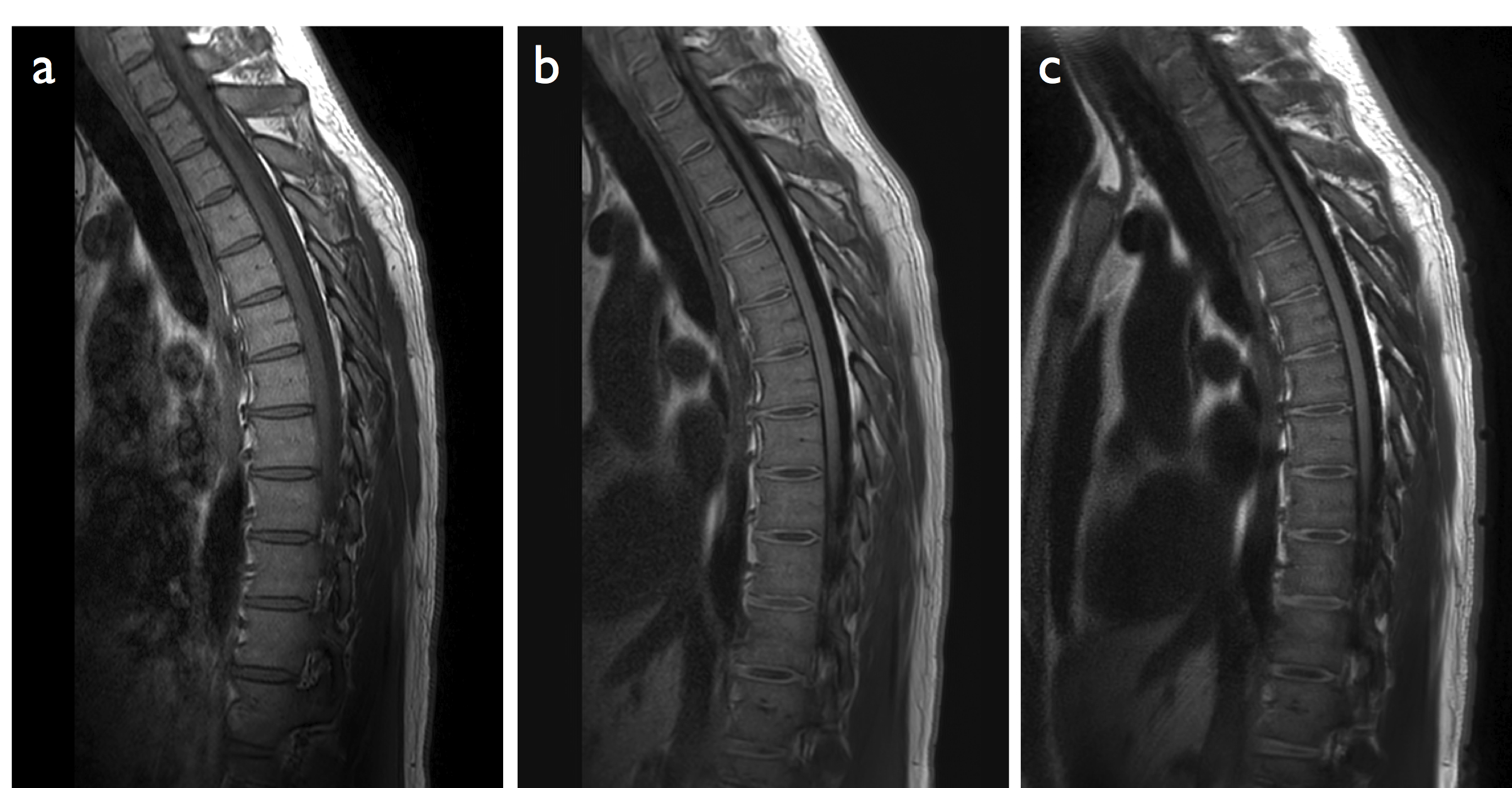
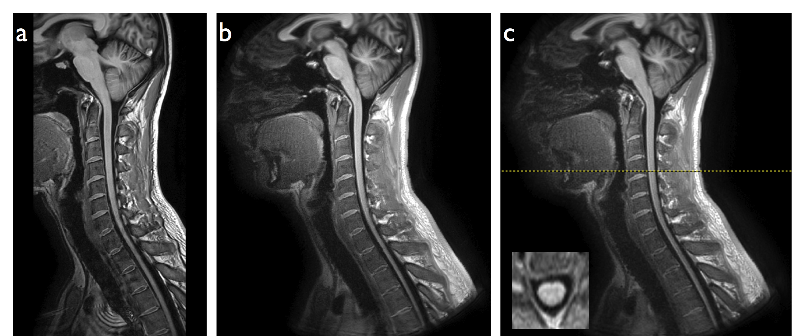
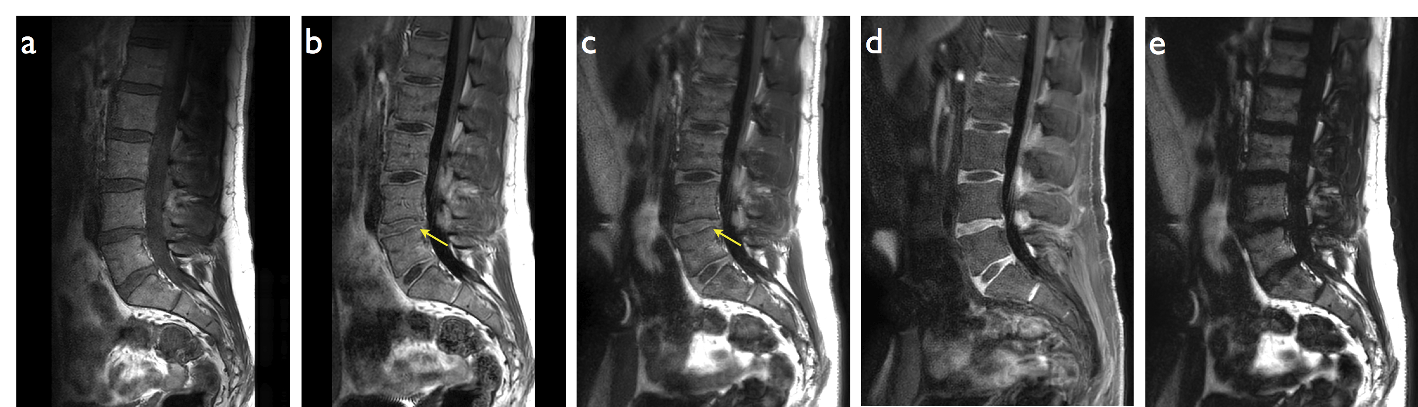
Figures 2-4 show representative thoracic, cervical, and lumbar spine images for the Cartesian and spiral acquisitions. Compared to the TSE images, the disc annuli are relatively bright and the discs relatively dark and the cord delineation better in the MPRAGE images. Residual foldover artifacts can be seen inferior in the cervical spine images (figure 3). As highlighted in figure 4, the spiral acquisition allows for the reconstruction of separate fat and water images. This may provide some advantage over the Cartesian acquisitions which would require additional scan time to produce separate fat and water images.
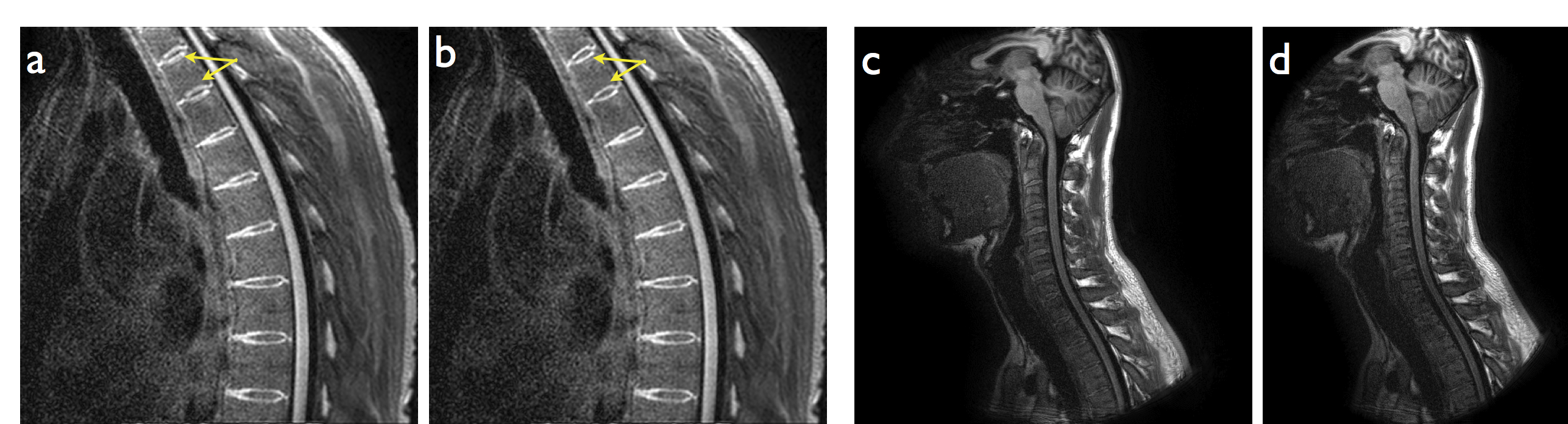
Spiral deblurring was observed to be successful in all image regions. However, blurriness is seen in the superior and inferior extremes of the images due to the effects of concomitant gradient fields. As shown in figure 5a, this blurriness from concomitant field effects can be corrected. An example of image data from an elliptical FOV spiral acquisition (f = 1.3) is shown in figure 5d. The current reconstruction pipeline does not support concomitant field correction or elliptical FOV spiral reconstruction. As such, these images were reconstructed offline and did not benefit from geometric warping correction and other corrections typically applied to images reconstructed at the scanner.
The overall relative SNR in the spiral images (particularly in the vertebrae) is lower than would be expected given the scan parameters. Spiral acquisitions can more efficiently make use of a long per shot readout time to increase SNR. This allows a spiral acquisition to yield equivalent or higher SNR to a similar Cartesian acquisition while requiring a total scan time that is shorter. However, the spiral data shown here appear to yield similar SNR to the Cartesian data for comparable scan times. This SNR discrepancy is an ongoing area of investigation.
Conclusion
This work has demonstrated that spiral MRI is suitable for T1 weighted imaging of the spine. Future work will seek to address residual artifacts from e.g. concomitant fields and further explore the SNR advantages of spiral.Acknowledgements
This research was funded in part by a grant from Philips Healthcare.References
1. Li Z et al. “Sliding-slab three-dimensional TSE imaging with a spiral-In/Out readout”, Magn Res Med (2015); 75:729-738.
2. Li Z et al. “Arterial spin labeled perfusion imaging using three-dimensional turbo spin echo with a distributed spiral-in/out trajectory”, Magn Res Med (2015); 75:266-273.
3. Hu HH et al. “Assessment of Cerebral Blood Perfusion Reserve with Acetazolamide Using 3D Spiral ASL MRI: Preliminary Experience in Pediatric Patients”, Mag Res Imag (2016); doi: http://dx.doi.org/10.1016/j.mri.2016.08.019.
4. Li Z et al. “A Spiral Spin-Echo MR Imaging Technique for Improved Flow Artifact Suppression in T1-Weighted Postcontrast Brain Imaging: A Comparison with Cartesian Turbo Spin-Echo” Am J Neuroradiol. (2016); 37:642-647.
5. Ellingson BM et al. “High-resolution in vivo diffusion tensor imaging of the injured cat spinal cord using self-navigated, interleaved, variable-density spiral acquisition (SNAILS-DTI)”, Mag Res Imag (2010); 28:1353-1360.
6. Blumenkrantz G et al. “A feasibility study of in vivo T1ρ imaging of the intervertebral disc”, Mag Res Imag (2006); 24:1001-1007.
7. Brown JE et al. “A hemodynamic response function for functional MRI of the cervical spine using motor and nociceptive paradigms” Joint ISMRM-ESMRMB Scientific Meeting & Exhibition, Berlin, 2007. p. 549.
8. Nair G et al. “Optimized T1-MPRAGE Sequence for Better Visualization of Spinal Cord MS Lesions at 3T” Am J Neuroradiol. (2013); 34:2215-2222.
Figures