1397
Compensation for Distribution of Receiving Sensitivity in Body Coil1Healthcare Business Unit, Hitachi, Ltd., Tokyo, Japan
Synopsis
We propose a new method to compensate for distribution of receiving sensitivity in a body coil. It corrects a shading artifact that remains after compensation based on sensitivity ratio of surface and body coils. The method utilizes body coil sensitivity taken in advance with an uniform phantom. The body coil sensitivity is transformed by referring the ratio of intensity between channels. The method is intrinsically insensitive to tissue contrast because it is cancelled by taking ratio. The method is useful when the reference image has strong tissue contrast. The effect of proposed method is examined by phantom and volunteer study.
Purpose
The purpose of this study is to propose a new method for shading correction which is insusceptible to tissue contrast in reference images.Introduction
In MRI, image intensity is varied with coil sensitivity. There are various methods to correct the intensity inhomogeneity. One of those methods is that reference images are taken with both surface and body coils and main images with the surface coil are divided by the reference-intensity ratio of the surface coil to the body coil.1 It reduces steep inhomogeneity caused by the surface coil to gentle inhomogeneity of the body coil. The inhomogeneity of the body coil is, however, not negligible in a high magnetic field system. To compensate for the distribution of receiving sensitivity in the body coil, a method utilizing low-pass filtered reference images has been proposed.2 The method assumes that the reference image reflects coil sensitivity rather than tissue contrast. The assumption is, however, not always true. Especially in acoustic noise reduction, tissue contrast is likely to become strong because of long TE caused by slow switching of a gradient field. In such a situation, sensitivity compensation which is insusceptible to tissue contrast in the reference image is required.Methods
Here, we will explain how to obtain sensitivity distribution in the body coil which is used for the compensation.
First, an uniform large phantom is scanned with the body coil in advance and the following two relations are obtained. The first relation f1(r) is sensitivity of the body coil at a position r. It is directly derived from image intensity because the phantom is uniform. The second relation g1(r) is intensity ratio of two channels in the body coil. In this study, the body coil is birdcage and has two channels.
Next, the reference image of a subject is acquired and the intensity ratio g2(r) for the subject is obtained. To derive sensitivity distribution f2(r) for the subject, we make an assumption that sensitivity distribution for each channel is transformed with same coordinate transformation when the substance in the body coil is changed. The coordinate transformation h(r) is derived to minimize
$$\sum\left[\left\{ \tan\left(g1\left(h\left(r\right)\right)\right)-\overline{\tan\left(g1\left(h\left(r\right)\right)\right)}\right\}-\left\{\tan\left(g2\left(r\right)\right)-\overline{\tan\left(g2\left(r\right)\right)}\right\}\right]^{2}.$$
The sensitivity distribution f2(r) for the subject is determined by f2(r) = f1(h(r)). In this study, we use scaling and translation in plane as the coordinate transformation.
For examination of compensation effect, medium-size
phantom, small phantom and volunteer are scanned with a 1.5T imaging system. Main
images are acquired with 2D gradient echo sequence with TR/TE = 500/14ms and FA
= 18 degrees. Reference images are acquired with 3D spoiled gradient echo
sequence with TR/TE = 8.8/ 4.4ms and FA = 5 degree. In volunteer imaging,
another reference image is acquired with different TR/TE = 4.0/1.5ms.
Results
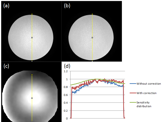
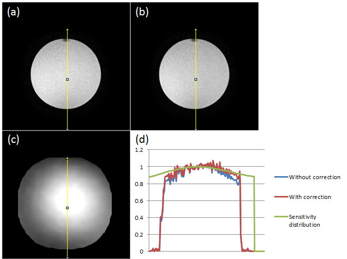
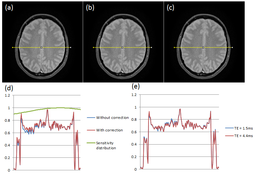
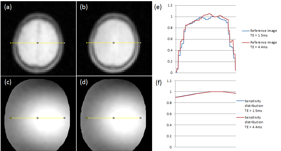
Figure 1 shows main images without correction, with correction and estimated body-coil sensitivity in the medium-size phantom. With correction, intensity is recovered about half, that is, 20% decrease is recovered to 10% decrease. Figure 2 shows results in the small phantom. Intensity recovery is similar to the medium-size phantom. The estimated sensitivity distribution changes in response to the size and position of a phantom. Figure 3 shows results in volunteer images. It shows main images without correction, with correction using reference images of different TE and profiles from main images and estimated body-coil sensitivity. With correction, a shading artifact in the direction of right to left is corrected. The result of TE = 4.4ms is same as TE = 1.5ms. Figure 4 shows reference images with the body coil and estimated sensitivity in different TE. Though the contrast in a reference image is different in different TE, estimated sensitivity is almost identical.
Discussion
The new method recovers the intensity about half of the original decrement in phantom study. The transformation of sensitivity distribution well corresponds to the position of a phantom. The residual shading artifact is possibly caused by distribution of transmitting sensitivity because the main images are taken with low FA and are likely to be affected with transmitting inhomogeneity.
The correction of a shading artifact in volunteer study is in success in spite of simple transformation of scaling and translation. The reason for this will be that the difference in magnetic permeability, electric conductivity and permittivity is small in brain parenchyma3 and there is not local change of sensitivity.
Conclusion
A new method for shading correction which is insusceptible to tissue contrast in a reference image is proposed. It is applicable to a reference image with long TE for acoustic noise reduction. The effect of proposed method is examined by phantom and volunteer study.Acknowledgements
No acknowledgement found.References
1. Ingwer C. Carlsen and Dye Jensen. Reconstruction Algorithm for Images Obtained with Flexible Multi-Element Synergy Coils. Proc., SMR, 2nd Annual Meeting, 1994;834.
2. Leon Axel, Jay Constantini, and John Listerud. Intensity Correction in Surface-Coil MR Imaging. AJR 148:418-420, February 1987.
3. Amane Takei, Kouhei Murotani, Shinobu Yoshimura and Hiroshi Kanayama. Finite element analysis for microwave frequency electromagnetic fields using numerical human models. Japan Society for Simulation Technology, Vol.4, No.3, pp.81-95, 2012.
Figures