1387
Robust k-space trajectory mapping with data readout concatenation and automated phase unwrapping reference point identification1Radiology and Radiological Sciences, Vanderbilt University Medical Center, Nashville, TN, United States, 2Vanderbilt University Institute of Imaging Science, Vanderbilt University Medical Center, Nashville, TN, United States, 3Biomedical Engineering, Vanderbilt University, Nashville, TN, United States, 4Neuroimaging Research, Barrow Neurological Institute, Phoenix, AZ, United States
Synopsis
A fundamental challenge when mapping k-space trajectories that require unwrapping of phase proportional to position in k-space is the accrual of phase during gradient prewinders and phase encodes, which are not sampled. To overcome this challenge, we present a simple method using data readout concatenation and automated phase unwrapping reference point identification to robustly map a broad range of trajectories. This approach works for any k-space trajectory for which data readouts can be connected to provide a path crossing near the center of k-space from which 1D phase unwrapping can be performed.
Purpose
This works describes an approach for robust mapping of k-space trajectories for which not all transitions in k-space are captured by data acquisition. We build upon the well-known trajectory mapping method based on phase accrual in an excited slice offset from isocenter that is orthogonal to a single active encoding gradient as described by Duyn et al. [1] and improved by others [2-3]. A fundamental challenge when applying such methods is the unwrapping of phase that is proportional to position in k-space. Many common trajectories include gradient prewinders in the frequency encode direction and/or phase encoding gradients causing phase accrual in the trajectory mapping sequence that are not captured by the standard data acquisition of the pulse sequence. To overcome this challenge, we present a simple method using data readout concatenation and automated phase unwrapping reference point identification to robustly map a broad range of trajectories including full-echo radial, PROPELLER, EPI and standard Cartesian.Methods
Software (R5.1.7) was customized to enable the mapping for any gradient echo pulse sequence on a 3 Tesla Achieva scanner (Philips Healthcare, Best, The Netherlands). The fundamental alteration was an extension to the gradient object to enable the runtime deactivation (nulling) or inversion of a gradient for each physical axis. Any sequence could be mapped using four repetitions per mapped axis. An additional repetition was collected using unmodified gradients to acquire k-space with normal spatial encoding. Hence, 2D sequences in one physical plane could be mapped with 4+4+1=9 repetitions, and 4+4+4+1=13 repetitions could map angulated 2D and 3D sequences. The sample point with peak magnitude in the normally encoded k-space data was identified as the reference point for 1D phase unwrapping in the time dimension of the trajectory mapping data.
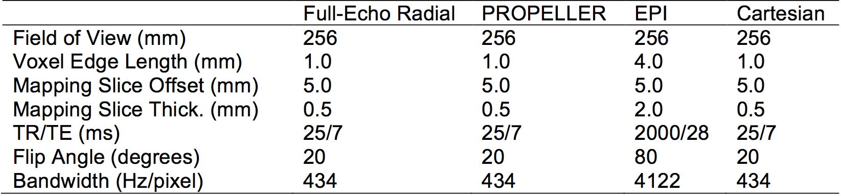
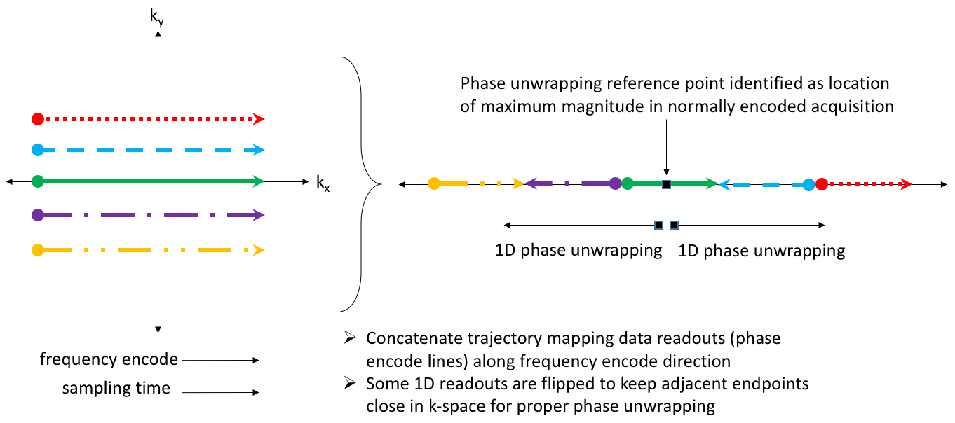
The identified reference point does not have to be exactly at the center of k-space. It only needs to be within one phase wrap of the trajectory mapping phase. For a trajectory such as full-echo radial, such as point near the center of k-space appears in every data readout and no data concatenation is required. For other trajectories such as PROPELLER, EPI and standard Cartesian, most individual data readouts do not pass close enough to the center of k-space to be robustly unwrapped. Therefore, it is necessary to use knowledge of the intended trajectory to concatenate data readouts at points known to be close in k-space. This data readout concatenation step makes no assumptions about exact position in k-space. Figure 1 shows a diagram of this approach applied to several readouts sampling a rectilinear grid that could appear in a PROPELLER or standard Cartesian trajectory. After the appropriate readout concatenation, phase unwrapping and conversion to k-space coordinates is performed. The approach was validated using full-echo radial, PROPELLER, EPI and Cartesian scans of a 17 cm spherical gel phantom using a single-channel transmit receive bird cage coil. Acquisition details are listed in Table 1.
Results and Conclusion
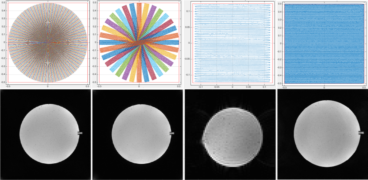
Figure 2 shows mapping results and reconstructions for the tested trajectories. All trajectories are successfully mapped despite not acquiring phase accrual during prewinder and phase encode gradients. These results demonstrate that the challenge of mapping of k-space trajectories containing prewinders and phase encodes can be overcome using the appropriate data readout concatenation and automated phase unwrapping reference point identification. This approach works for any k-space trajectory for which data readouts can be connected to provide a path crossing near the center of k-space from which 1D phase unwrapping can be performed.Acknowledgements
This work was supported in part by funding from NIH NIDDK R01 DK105371.References
1. Duyn JH, Yang Y, Frank JA, van der Veen JW. Simple correction method for k-space trajectory deviations in MRI. JMR. 1998;153:150–153.
2. Gurney P, Pauly JM, Nishimura DG. A simple method for measuring B0 eddy currents. In: Proc. 13th Scientific Meeting, ISMRM, Miami, FL; 2005:866.
3. Brodsky EK, Klaers JL, Samsonov AA, Kijowski R, Block WF. Rapid measurement and correction of phase errors from B0 eddy currents: Impact on image quality for non-cartesian imaging. MRM. 2013;69:509–515.
Figures