1369
A novel MR Elastography transducer concept based on a rotational eccentric mass: the gravitational transducer1Division of Imaging Sciences and Biomedical Engineering, King's College London, London, United Kingdom, 2Radiology, Academic Medical Center, Amsterdam, Netherlands, 3Biomedical NMR, Eindhoven University of Technology, Eindhoven, Netherlands, 4Preclinical and Translational MRI, Academic Medical Center, Amsterdam, Netherlands
Synopsis
Several transducer designs are in use for MR Elastography, based mainly on either pneumatic (or compressed) air or on electromagnetic engine-coils fixed to a lamella. These technologies have enabled significant development within the MR Elastography community and shaped its clinical application. In this abstract, we build on these concepts to introduce a novel transducer that limits image artefacts, limits resonant frequencies and vibrational impurities, and importantly preserves transducer amplitude with frequency; effectively improving the quality of the wave data that can be encoded with MR.
Background
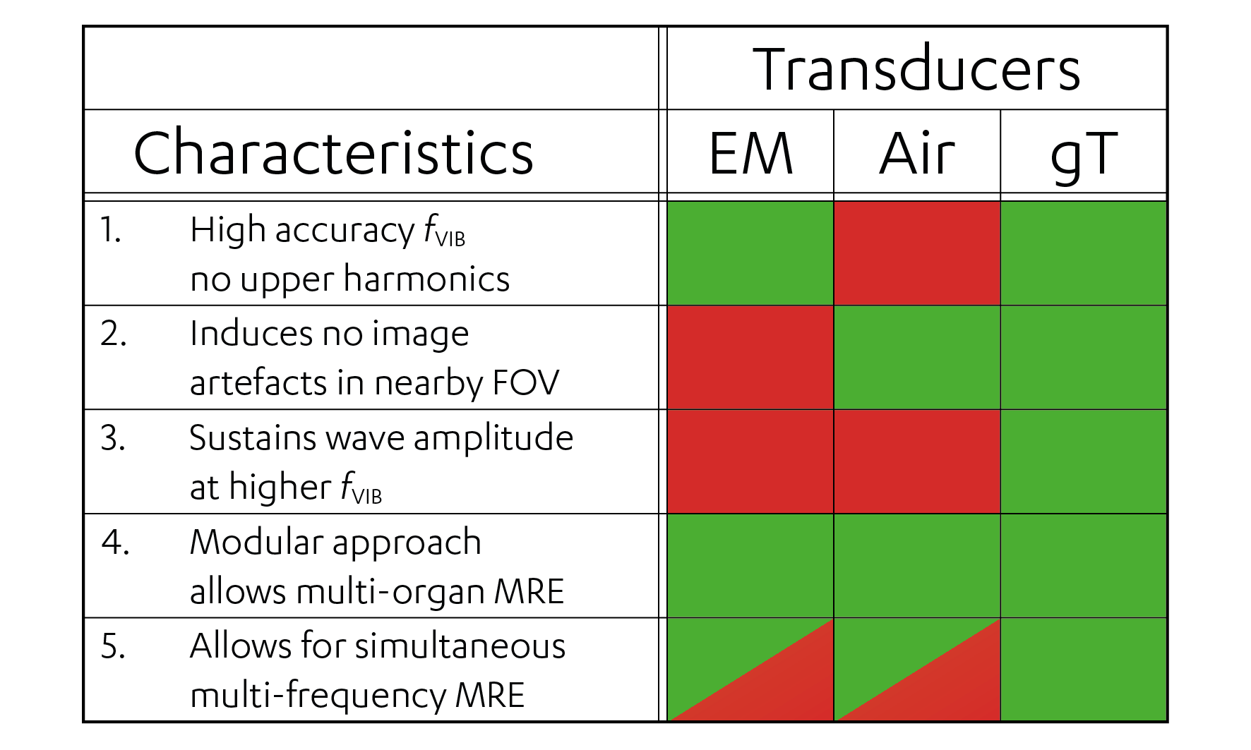
MR Elastography (MRE) is based on the application of low-frequency vibrational waves encoded in the MR phase using synchronized motion encoding gradients (MEG), from which viscoelastic maps are estimated1. Several transducer setups to generate vibrational wave have been proposed2, based mainly on either pneumatic (or compressed) air3,4 or on electromagnetic engine-coils5-7. The pneumatic transducer is currently the only FDA-approved setup, for liver fibrosis grading only. MRE has yet to make a significant impact in other diagnostic areas. To make this leap requires more reliable estimates of viscoelasticity, by more sensitive motion-encoding, higher spatial resolution in clinically acceptable scan times and improved vibrational waves. The latter requires several transducer-related issues to be addressed: (1) vibrational frequency (fVIB) accuracy, (2) induced image artefacts, (3) preserved transducer amplitude at higher fVIB, (4) modularity of the setup and (5) inherent capability of multi-frequency MRE.Purpose
In this study we present a new MRE gravitational transducer (gT) concept based on a rotating eccentric mass. The gT addresses the aforementioned issues and delivers accurate vibrational waves with constant displacement regardless of fVIB to allow unparalleled estimation of viscoelastic properties in a range of clinical contexts.Materials and Methods
Gravitational transducer concept
The concept (Fig. 1)
consists of (A) a 4 Nm stepper motor
(60BYGH401-03, CNC4U) with controller unit (MCC-01 32/48, Pythron) and (B) a rotating fibre glass rod attached
to (C) the gravitational transducer.
The transducer can be detached and other designs attached. Shown in Fig. 1 is a gT for liver MRE. The transducer
is a custom 3D ABS plastic printed casing that houses a (D) PEEK rod glued to (E)
two PEEK bearings. Two timing pulleys and belt (F) with a 1:3 ratio connect the rotating fibre glass rod (B) to D. The (G) eccentric mass
is a custom wedge-shaped, cement-filled 3D ABS plastic print attached to D. As the eccentric mass rotates, it
exerts a centrifugal force that is transmitted to the whole casing via the (E) PEEK bearings. This centrifugal force follows the
rotational frequency squared (ω2), resulting in a net constant displacement amplitude (given by acceleration
divided by ω2). By adding (an) additional
PEEK rod(s) with a mass and different gear ratio(s), inherent multi-frequency
experiment are possible.
Stepper
motor and controller
The stepper motor controller is synchronized to TTL-signals
from the MR system using a custom-made script in Phytron MiniLog format. As nominal
motor settings resulted in a loss of correct angular position relative to the first
(reference) position, the script was further customized to ensure the angular
stability by checking stepper motor position relative to the reference position
and de- or accelerating as required throughout the next run period between
TTL-signals (~1s).
Phantom
measurements
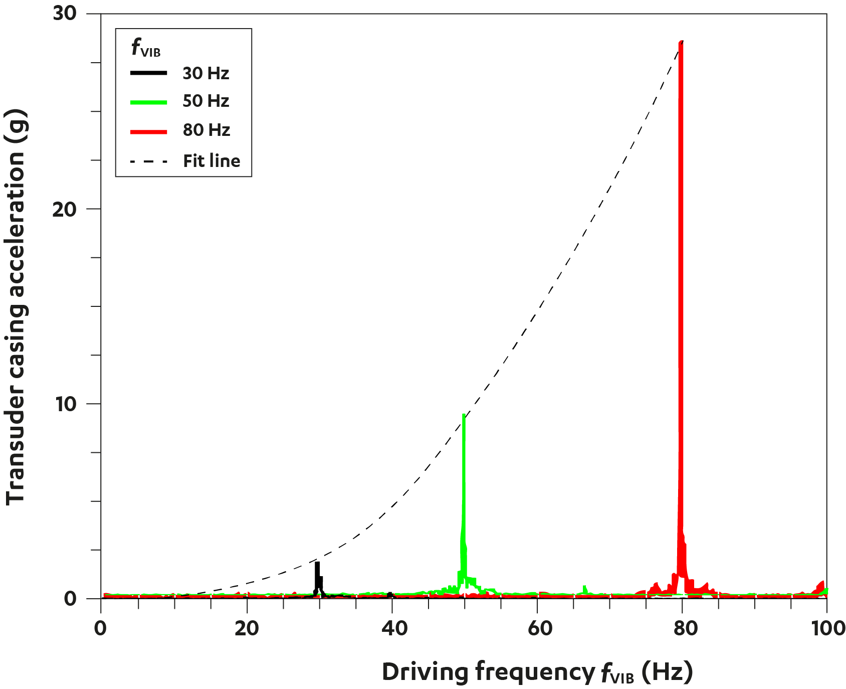
To test the fVIB
accuracy and the behaviour of the transducer amplitude at several fVIB, we measured the acceleration
spectrum at fVIB of 30, 50
and 80 Hz using the gT attached to an ultrasound gel phantom. Spectra were
recorded using an ADXL 345Z accelerometer controlled by a Raspberry Pi
(Raspberry Pi Foundation, Cambridge, United Kingdom).
In vivo
MRI
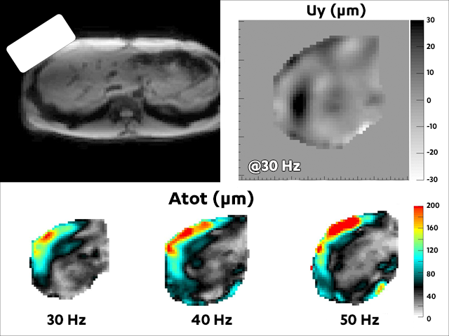
As proof-of-principle, we performed MRE of the liver using
the gT on a clinical 3T MR Scanner (Achieva, Philips Healthcare, The
Netherlands). Acquisition was according to Garteiser et al.8 with fMEG = 160Hz, fVIB = 30, 40
and 50 Hz and eight wave images per wave cycle.
Results and Discussion
Fig. 2 shows the effect of stabilization on the accuracy of the stepper driver: with stabilization the angular position hovers around 0°; without stabilization, there is a 65° shift between start- and end-acquisition (~1min) causing a substantial phase shift in the data, hampering reliable viscoelasticity estimation. Fig. 3 shows the narrow frequency response of the transducer at 30, 50 and 80 Hz. Mind the absence of any upper harmonics demonstrating the linearity of the system! The line-of-fit shows that acceleration increases with , as predicted by theory for such a system. As displacement is acceleration divided by, transducer amplitude is constant with frequency. Fig. 4 illustrates the considerable and constant wave penetration as fVIB increases, using in-vivo liver data, in absence of any image artefacts. Finally, Fig. 5 summarizes the characteristics of several transducer concepts currently available. The data presented here show that the gT provides very accurate vibrational waves with constant amplitude, in absence of higher harmonics or any image artefact.Conclusion
The gravitational transducer presented here provides on-resonance fVIB with no upper harmonics, no image artefacts and constant wave amplitude as fVIB increases. The combination of these characteristics makes it well-suited for MR Elastography applications in a wide range of clinical contexts.Acknowledgements
This project has received funding from the European Union’s Horizon 2020 research and innovation programme under grant agreement No 668039.
References
1. Glaser KJ, Manduca A, Ehman RL. Review of MR elastography applications and recent developments. J Magn Reson Imaging. 2012;36:757-774.
2. Uffmann K, Ladd ME. Actuation systems for MR elastography: design and applications. IEEE Eng Med Biol Mag. 2008;27:28-34.
3. Mariappan YK, Rossman PJ, Glaser KJ, et al. Magnetic resonance elastography with a phased-array acoustic driver system. Magn Reson Med 2009;61:678-685.
4. Braun J, Hirsch S, Heinze T, et al. Feasibility of a new actuator type for magnetic resonance elastography based on transient air pressure impulses. Proc. Intl. Soc. Mag. Reson. Med. 2015;23:1826.
5. Sahebjavaher RS, Frew S, Bylinskii A, et al. Prostate MR elastography with transperineal electromagnetic actuation and a fast fractionally encoded steady-state gradient echo sequence. NMR Biomed. 2014;27:784-794.
6. Forsgren MF, Noren B, Kihlberg J, et al. Comparing hepatic 2D and 3D magnetic resonance elastography methods in a clinical setting - Initial experiences. Eur J Radiol Open 2015;2:66-70.
7. Runge JH, Nelissen JL, de Graaf L, et al. A compact and easy to handle set-up for high quality MR Elastography of the breast. Proc. Intl. Soc. Mag. Reson. Med. 2016;24:2478.
8. Garteiser P, Sahebjavaher RS, Ter Beek LC, et al. Rapid acquisition of multifrequency, multislice and multidirectional MR elastography data with a fractionally encoded gradient echo sequence. NMR Biomed. 2013;26:1326-1335.
Figures