1328
New method to characterize and correct with sub-µs precision gradient delays in bipolar multi-spoke RF pulses1UNIRS, CEA/DRF/I2BM/Neurospin, Gif-sur-Yvette, France, 2Siemens Healthcare, Saint Denis, France
Synopsis
Small gradient delays with respect to radiofrequency (RF) pulses can have disastrous effects on the performance of bipolar spokes RF pulses employed in parallel transmission (pTx) to mitigate RF field inhomogeneity problems. This work reports a new method to characterize this delay with a precision of ~20 ns, shown to appear necessary for high performance pTx. By the same token, the same physics principles underlying the method suggest a way to correct for it by simply phase-shifting every second spoke RF pulse. The technique is validated with measurements on a water phantom and on an adult volunteer at 7T.
Purpose
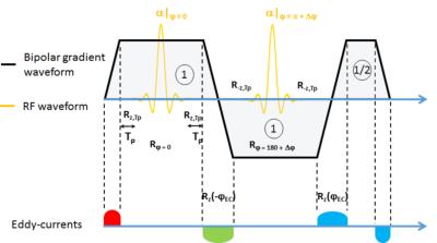
Multi-spokes RF pulses constitute a powerful approach in pTx to mitigate the RF inhomogeneity problem at ultra-high field in 2D. To date experimental demonstrations have made extensive use of unipolar configurations due to their larger robustness against eddy-currents and gradient delays1,2,3 compared to bipolar implementations. Different MR methods to characterize this delay exist but may be SNR limited4 or may require additional equipment5. The method reported here relies on a simple $$$\alpha_{0^{\circ}}-\alpha_{180^{\circ}+\Delta\!\phi}$$$ bipolar 2-spoke experiment (Fig.1). In the absence of gradient delays and eddy-currents, this pulse sequence yields zero signal when $$$\Delta\!\phi=0$$$. As we shall demonstrate, gradient delays however will yield an effective phase-shift of the second RF pulse proportional to the carrier frequency offset used to excite the slice of interest. By determining the $$$\Delta\!\phi$$$ value restoring a minimum of signal, the gradient delay thus can be deduced with good accuracy.Method
The delay characterization measurement is depicted in Fig.1. The blips shown in the figure correspond to zero-order eddy-currents ($$$\Delta\!B_0(t)$$$ envelopes) inherent to the presence of slice selection gradient ramps and which need to be modelled for an accurate analysis. With spoiled GRE sequences, the first (red blip in Fig.1) and last (blue blip) eddy-currents, the refocusing gradient lobe, the first rising gradient slope before the first RF pulse and the descending gradient slope after the second pulse do not affect the flip angle and thus shall be ignored. During the first gradient lobe and with a gradient delay $$$\Delta\!t$$$, the gradient during $$$T_p-\Delta\!t$$$ induces a rotation $$$R_{z,T_p-\Delta\!t}$$$ on the spins around $$$z$$$ with an angle of rotation proportional to $$$T_p-\Delta\!t$$$. The RF pulse during the first plateau generates the rotation $$$R_{\phi=0}$$$ where, importantly, $$$\phi$$$ corresponds to the global phase of the RF pulse and not the axis of rotation (which may be pointing between the $$$z$$$-axis and the transverse plane). The second pulse, except for the phase change, should be the time-reversed of the first. The rotation induced by the second pulse thus is $$$R_{\phi=\pi+\Delta\!\phi}$$$. The residual eddy-current between the two RF sub-pulses (green envelope in Fig.2) generates $$$R_z(-\phi_{\text{EC}})$$$, i.e. a rotation of angle $$$-\phi_{\text{EC}}$$$ around $$$z$$$. In the absence of a static $$$\Delta\!B_0$$$ offset, the rotation matrix can be shown to be equal to:
$$R_{\text{TOT}} = R_{-z,T_p-\Delta\!t}R_{\phi=\pi+\Delta\!\phi+\phi_{\text{EC}}-2\delta}R_{\phi=0}R_{z,T_p-\Delta\!t},$$
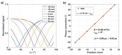
where $$$\delta=\gamma{G_z}\Delta_t$$$, $$$G$$$ being the gradient amplitude and $$$z$$$ the slice position. The eddy-current and gradient delay thus effectively induce a phase-shift on the second RF pulse. If $$$\Delta\!\phi=2\delta-\phi_{\text{EC}}$$$, then the rotation matrix above becomes Identity and there should be no signal. Thus by determining at different slice locations the $$$\Delta\!\phi$$$ value which returns a minimum of signal, the delay $$$\Delta\!t$$$ can be recovered by linear regression of $$$\Delta\!\phi$$$ versus $$$z$$$. Axial measurements were performed at 7T at -25,-20,-10,0,10,20 and 25 mm from the isocenter on a water phantom and $$$\Delta\!\phi$$$ was swept across the interval $$$[-90^{\circ};90^{\circ}]$$$. Once the delay and zero order eddy-current terms $$$\Delta\!t$$$ and $$$\phi_{\text{EC}}$$$ were recovered, their prospective correction was implemented in tailored bipolar 2-spoke configurations2 on the same phantom and in vivo with multi-slice T2*-weighted GRE protocols (25 slices, TE=15 ms, TR=936 ms, FA=30°, 0.5×0.5×2 mm3 voxels), by phase-shifting the second sub-pulse according to the slice locations. The results were compared to the unipolar 2-spoke implementations as a reference.Results
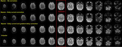
Figure 2 reports the phase sweep experiment on the phantom. Linear regression on the second sub-plot returned $$$\phi_{\text{EC}}=-8^{\circ}$$$ and $$$\Delta\!t=-2.69\pm0.02$$$ µs. This delay, if not corrected, can induce an effective phase shift of the second sub-pulse as large as 198° for $$$G=$$$40 mT/m and $$$z=$$$6 cm, which explains why this effect can quickly become disastrous for multi-spoke pulse performance. Fig.3 (phantom) and Fig.4 (in vivo) illustrate this behavior with signal voids appearing away from the isocenter. In this setup, after correction of the gradient delay and eddy-current by phase-shifting the second pulse, the results of the bipolar configuration became very similar to the ones obtained with the unipolar configuration.Discussion and conclusion
The effective phase-shift induced by a gradient delay being proportional to the carrier frequency offset, an accuracy better than 0.1 µs is desired for high performance bipolar spokes implementations, a performance hardly obtainable with time-shifting methods constrained by RF raster times typically ≥ 1 µs. Because the phase of RF pulses is well-controlled in modern MR equipment, with ~20 ns precision, the method reported here is simple and appears to meet this demand. By the same token, it yields as a bonus the zero-order eddy-current phase correction that should be applied for optimal results.Acknowledgements
The research leading to these results has received funding from the European Research Council under the European Union’s Seventh Framework Program (FP7/2013-2018), ERC Grant Agreement n. 309674.
References
[1] Sharma et al. MRM 2016 ;74 :747-755. [2] Gras et al. MRM; doi 10.1002/mrm.26491. [3] Tse et al. ISMRM 23rd 2015; p. 0546. [4] Davies et al. MRM 2005;53:231-236. [5] Brunner et al. NMR in biomed 2016;29:1162-1172.Figures


