1322
Selective excitation using Multix and Active contouR Technique1Medical Imaging Research Centre, Dayananda Sagar Institutions, Bangalore, India, 2Philips Innovation Campus, Bangalore, India
Synopsis
Selective excitation using Multix and Active contouR Technique (SMART) proposed here, is an optimization framework for the joint design of k-space trajectories and radio frequency pulses. The combination of active contour and the multix has been done for the first time which allows the use of arbitrary k-space trajectories. SMART has been prospectively implemented on two channel 3T Philips Ingenia system for different geometric shapes and organs to demonstrate arbitrary volume selective excitation and has shown improved excitation profile. Current and future work involves implementation on in-vivo studies.
Purpose
Selective excitation using Multix and Active contouR Technique (SMART) has been used to demonstrate arbitrary k-space trajectory design and implementation for selective excitation for arbitrary shape . Implementation was done using optimized Excitation field of View (XFOV) shape dependent k-space trajectories to achieve organ specific excitation and water suppression.Methods
In silico simulation: SMART was implemented using k-space trajectories obtained by the active contour method. Trajectories kx and ky are dependent on the desired excitation pattern XFOV. A single-shot excitation k-space trajectory designed based on contours derived from the active contour segmentation1 of excitation k-space. Figure 1 shows the psuedo code for SMART implementation. The following gradient parameters were used for in silico and in vitro phantom experiments: Gmax = 45mT/m and SR = 200mT/m/ms (specifications matched to a 3T Multix 2 channel transmit, Philips Ingenia). A trajectory was designed which supported 4mm X 4mm resolution, a FOV of 128mm X 128mm and an XFOV of 24mm X 24mm resulting in pulse duration (T) of 4ms. Optimized gradients Gx and Gy oscillate in a manner so that the kx and ky coordinates are optimally sampled by subjecting it to maximum gradient amplitude (Gmax) and slew rate (SR) constraints. Optimized gradients and the integration matrix were then provided to the convex optimization tool (cvx)2 to optimize RF pulses3. Normalized Root Mean Square Error (NRMSE) between the obtained magnetization and desired magnetization was computed to quantify excitation error. SMART was implemented for different geometric shapes and organ shape such as liver, and compared with the spatial domain method3. All the simulations were performed in Matlab 2013a, The Mathworks Inc., Boston MA. In vitro phantom study: SMART was implemented for two geometric shapes and an organ shape (liver). Prospective implementation was performed on the two channel 3 T Philips Ingenia using a spherical homogeneous CuSO4 phantom.Results
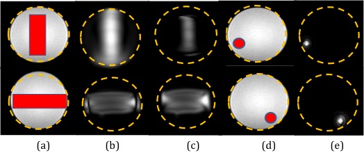
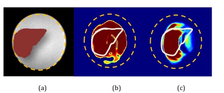
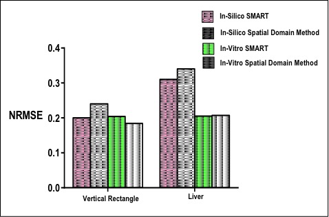
In silico : Figure 2 shows SMART implementation on a vertical rectangle and a liver shape. Results show SMART can excite target patterns with improved accuracy as compared to spatial domain method. Accuracy can be attributed to traversal of shape dependent excitation k-space. In vitro Phantom: Figure 3 shows comparison between SMART and spatial method for different geometrical shapes and the optimized gradients and RF pulses has resulted in more uniform and less erroneous excitation of the desired pattern. Figure 4 shows the excitation pattern of an arbitrary shape which is in the shape of liver implemented by SMART and the spatial domain method frameworks. Excitation is more at the centre in spatial domain method because of spiral excitation trajectory and SMART shows improved magnetization profile as the k-space trajectories samples the desired excitation pattern. The optimized gradients and two RF pulses simultaneoulsy excited the XFOV and effeciently worked for off centric spatial selective excitation as shown in Figure 4. Figure 5 shows the NRMSE with respect to the desired excited pattern for in silico and in vitro experiments for vertical shape and liver shape.Discussion and Conclusion
The combination of active contour and multix for the design of arbitrary k-space trajectories has been performed for the first time. This is an approach that is formulated as a convex optimization problem in the spatial domain and allows the use of arbitrary k-space trajectories. The results of these preliminary studies have offered an opportunity to demonstrate arbitrary volume selective excitation and has shown improved excitation magnetization profile to explore organ specific MRI as compared to the spatial domain method. Excitation error as observed with 2 channel transmit system can be reduced if the implementation is done on 8 channel, however current framework is independent of number of channels. Some of the considerations in the design of these pulses are (a) mask provided by the active contour (b) gradients amplitude and slew rate (c) the length of the pulse. SMART samples k-space directly based on the arbitrary shape due to the nature of active contour where as ref. 4 is a non-convex optimization framework, which tweaks a given trajectory. Current and future work future work involves implementation of this technique along with incorporation of local SAR constraints based on electromagnetic model simulation such as Virtual Human Model and in vivo studies.Acknowledgements
No acknowledgement found.References
References: (1) Kass.et.al., Snakes: Active Contour Models, IJCV, 1998 (2) Grant et.al,CVX tool, Copyright 2010. (3) Grissom.et.al, Spatial Domain Method for the Design of RF Pulses in Multi coil Parallel Excitation,MRM 2006 (4) Yip.et.al, Joint Design of Trajectory and RF Pulses for Parallel Excitation, MRM 2007Figures
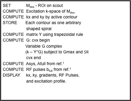
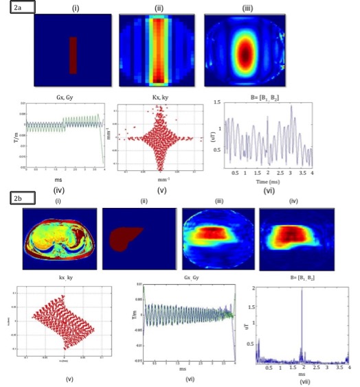
Figure 2 a: (i) XFOV (ii) Excited patterns for spatial domain method (iii) SMART (iv) Optimized gradients (v) k-space trajectory and (vi) RF pulse for Gmax varying from -0.025 T/m to 0.020 T/m, SR < 200 T/m/s
Figure 2 b: (i) Abdomen axial (ii) XFOV (iii) ) Excited patterns for spatial domain method (iv) SMART (v) k-space trajectory (vi) Optimized gradients and (vii) RF pulse for Gmax varying from -0.020T/m to 0.035 T/m, SR<200 T/m/s