1310
Unified Rigid Motion Compensation Using Wireless MR Active Markers for Simultaneous PET/MR Imaging of the Brain1Engineering Physics, Tsinghua University, Beijing, People's Republic of China, 2Gordon Center for Medical Imaging, Radiology, Massachusetts General Hospital, Harvard Medical School, Boston, MA, United States, 3Athinoula A. Martinos Centerfor BiomedicalImaging, Radiology, Massachusetts General Hospital, Boston, MA, United States, 4Radiology and Psychiatry, Stony Brook Medicine, Stony Brook, NY, United States
Synopsis
Head motion degrades image quality through loss of resolution in brain PET/MR. This work presents a wireless MR active marker based method to track and correct head motion for both PET and MRI. The proposed rigid motion correction method has been validated using a phantom study on a clinical PET/MR scanner.
Purpose
Head motion is a well-known source of resolution loss and image degradation in brain imaging. Many methods have been proposed to address this issue, e.g., using temporally segmented PET data,1 optical motion tracking systems,2,3,4 MR navigators,5 and MR active markers.6,7,8 Among them, the wireless MR active marker based method is particularly suitable for head motion correction in simultaneous PET/MR, because it is easy to set up, requires minimum changes to existing MR sequences, and enables continuous motion tracking with high temporal resolution (update every TR). In this work, we present a rigid motion correction method for PET and MRI using wireless MR active markers for simultaneous PET/MR imaging and demonstrated the feasibility of the proposed method using a phantom study.Methods
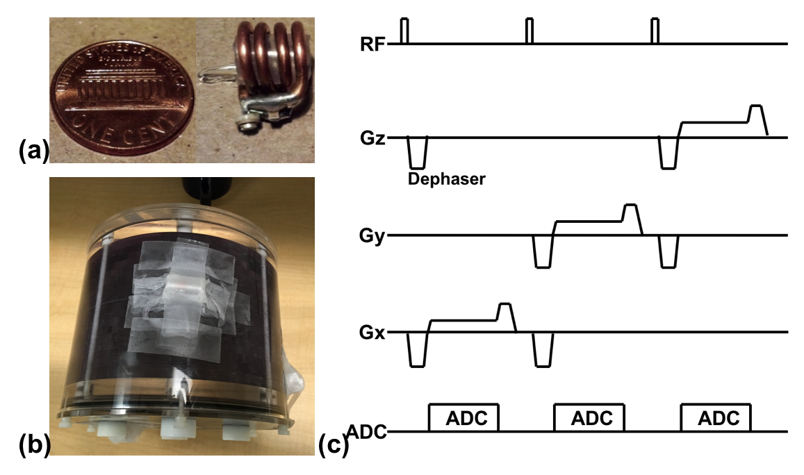
As shown in Fig. 1a, the wireless MR active marker consists of a spherical microsample cell enclosed by a solenoidal wireless MR microcoil. The sample cell was filled with water doped with 1.25 g/L NiSO4·6H2O and 5 g/L NaCl.8 MR signals from the wireless MR active markers are excited and received through inductive coupling between the wireless markers and the transmit and receive coils of the scanner. As shown in Fig. 1c, a navigator acquisition sequence is applied to obtain projection signals along three orthogonal directions. Due to the high filling factors of the microcoils, small flip-angle (<1°) RF excitation enables good visualization of the markers while largely suppressing the signal of the phantom. Dephasing gradients are used to further suppress signals from the phantom7,8. The total duration of the navigator sequence is ~15 ms. The positions of the wireless MR active markers are obtained from the projection signals; and the rotation matrix and translation vector between two consecutive navigator acquisitions are estimated using a singular value decomposition based algorithm.9 The resulting tracking information is incorporated into both MR and PET reconstruction.
To validate the proposed method, we performed a phantom study on a 3T whole-body simultaneous PET/MR scanner (Biograph mMR, Siemens Medical Systems, Erlangen, Germany). As shown in Fig. 1b, three wireless MR active markers were attached to the surface of a 3D Hoffman phantom (Data Spectrum Corporation, Hillsborough, NC), which was filled with water and 2.47 mCi 18F. A customized 3D GRE sequence was used to acquire MR data, where the navigator acquisition shown in Fig. 1c was added to the end of each TR of the sequence. Four simultaneous PET/MR acquisition sessions were performed. Between the consecutive sessions, the phantom was translated and rotated manually. In each session, a fully sampled 3D GRE data set was acquired with the following imaging parameters: FOV = 260x260x205 mm3, imaging matrix = 128x128x64, TE/TR = 4.8/75ms. The PET listmode data and attenuation maps were acquired simultaneously. PET list-mode data acquired in the session were reconstructed using OSEM.
Results
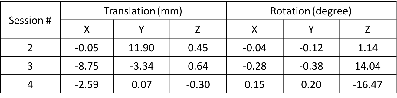
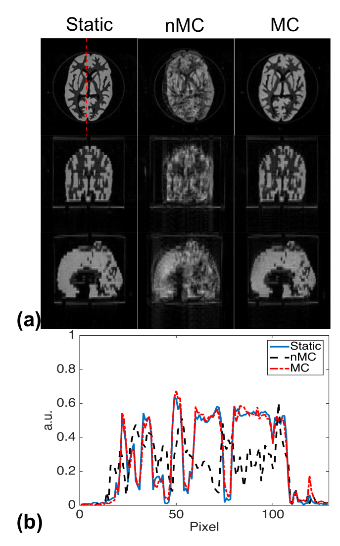
Table 1 lists the translation and rotation parameters estimated between the first and the following acquisition sessions using the acquired navigator signals. To simulate the effects of motion on MR images, four segments of k-space data were retrospectively extracted from each of the four GRE acquisitions to form a new data set that was fully sampled in k-space but corrupted by motion. Motion correction of this data set was performed by incorporating the rigid motion parameters estimated from the navigator signals to the forward model of an iterative reconstruction. Representative images of different reconstructions are shown in Fig. 2. Compared to the direct Fourier reconstruction of the motion-corrupted data (nMC), the proposed motion correction method (MC) significantly reduced motion artifacts and produced images very similar to the Fourier reconstruction of the motion-free data (Static).
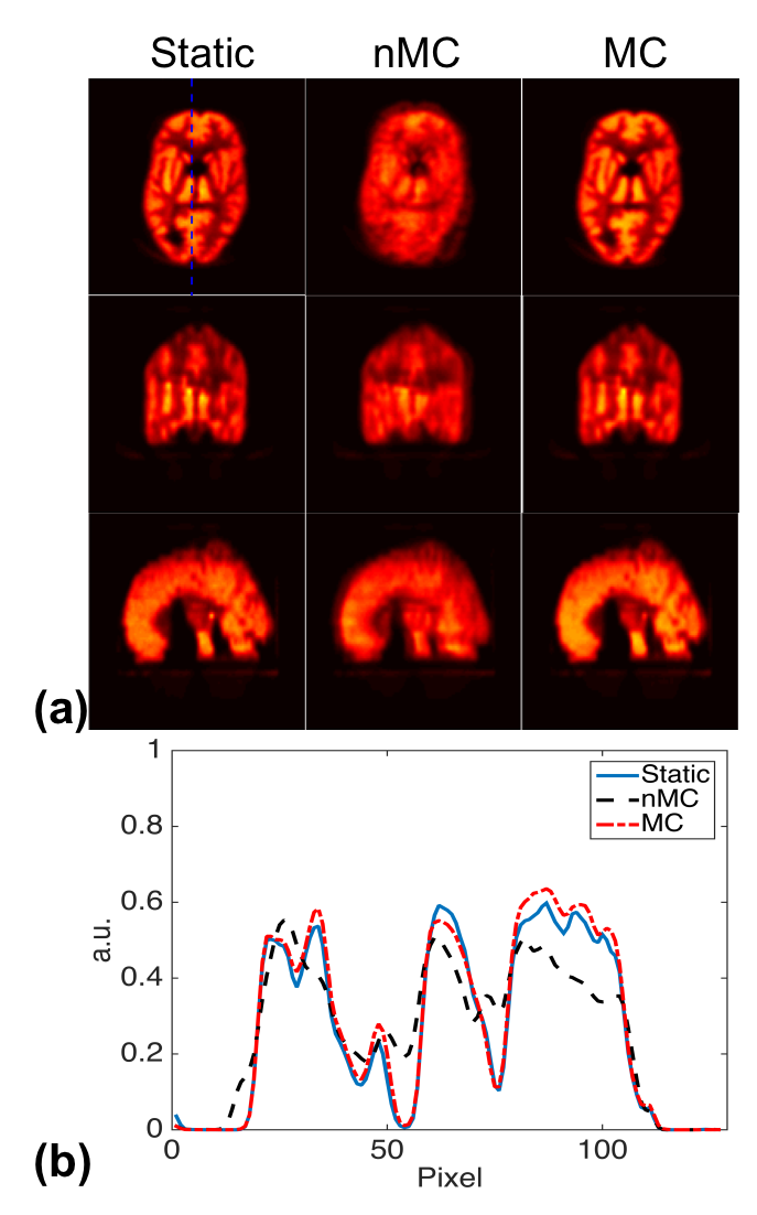
Figure 3 shows the PET reconstruction results. The PET reconstruction from the first acquisition was treated as the ground truth (Static). Directly averaging of the PET reconstructions of the four acquisitions (nMC) showed significant loss of resolution due to the motion between acquisitions. To correct motion, we aligned the reconstructed PET images together using the rigid motion parameters estimated from the navigator signals and then took the average. As can been seen, the blurring artifacts were significantly reduced in the motion corrected average image (MC).
Conclusion
This work demonstrates a wireless MR active marker based method to perform rigid motion correction for both PET and MRI in simultaneous PET/MR imaging. The proposed method has been validated using a phantom study on a simultaneous PET/MR scanner. It has potential for high-resolution brain PET/MRI imaging.Acknowledgements
This work was support in part by Tsinghua Top Open Program for Undergraduate Performing Research Abroad and by the National Institutes of Health; Grants: R03MH106994 and R21EB021710.References
1. Tellmann L, Fulton R, Pietrzyk U, et al., Concepts of registration and correction of head motion in positron emission tomography. Z Med Phys 2006;16:67-74.
2. Bloomfield P, Spinks T, Reed J, Schnorr L, Westrip A, Livieratos L, Fulton R, Jones, The design and implementation of a motion correction scheme for neurological PET. Phys Med Biol 2003;48:959–978.
3. Zaitsev M, Dold C, Sakas G, Hennig J, Speck O, Magnetic resonance imaging of freely moving objects: prospective real-time motion correction using an external optical motion tracking system. Neuroimage 2006;31:1038–1050.
4. Schulz J, Siegert T, Reimer E, et al. An embedded optical tracking system for motion-corrected magnetic resonance imaging at 7T. Magnetic Resonance Materials in Physics, Biology and Medicine, 2012, 25(6): 443-453.
5. van der Kouwe AJ, Benner T, Dale AM, Real-time rigid body motion correction and shimming using cloverleaf navigators. Magn Reson Med 2016;56:1019-1032.
6. Ackerman J, Offutt M, Buxton R, Brady T, Rapid 3D tracking of small RF coils. In Proc Soc Magn Reson Med 1986, pp. 1131–1132.
7. Huang C, Ackerman JL, Petibon Y, Brady TJ, El Fakhri G, Ouyang J, MR-based motion correction for PET imaging using wired active MR microcoils in simultaneous PET-MR: Phantom study. Med Phys 2014;41:041910.
8. Huang C, Ackerman JL, Petibon Y, Normandin M, Brady TJ, El Fakhri G, Ouyang J, Motion compensation for brain PET imaging using wireless MR active markers in simultaneous PET–MR: Phantom and non-human primate studies. Neuroimage 2014;91:129-137.
9. Arun KS, Huang TS, Blostein SD, Least-squares fitting of two 3-D point sets. IEEE Trans Pattern Anal Mach Intell PAMI 1987:698–700.
Figures