1292
Markerless Optical Tracking for Motion Correction in MR and PET/MR Imaging of the Brain1Department of Radiology, Stanford University, Stanford, CA, United States, 2Brain and Mind Centre, University of Sydney, Sydney, Australia
Synopsis
Optical prospective motion correction using markers attached to the patient’s head has been widely demonstrated to improve image quality in MRI of the brain. To simplify patient workflow, it would be helpful to remove the need for the marker. We have previously demonstrated markerless tracking using a stereo camera system, but this was done outside of the MR environment and used a 6-axis robot to validate tracking. In this work, we demonstrate markerless optical tracking in two volunteers during simultaneous MRI and use the markerless tracking data to retrospectively realign images.
Introduction and Purpose
Optical tracking systems that use a marker attached to the subject are an effective means to quantify head motion during scanning (1–5). This information can be used for prospective motion correction (6), which can prevent motion artifacts in most neuroimaging sequences. To make the method easier to use clinically, it would be useful if natural features on the patient could be tracked, avoiding the need to attach a marker. Our previous work has focused on validating markerless tracking outside the scanner bore, using a robotic test platform. In this work, we aimed to test markerless motion tracking during simultaneous MRI, with a view to future applications in prospective motion correction (for MRI) and retrospective motion correction (for PET).Methods
Cameras: We mounted two MR-compatible cameras on a standard 8-channel head coil using a polycarbonate rig (Figure 1). The cameras are normally used at our institution for single-camera head tracking of a rigid marker for prospective motion correction. We performed stereo camera calibration prior to the in vivo experiment, by moving a checkerboard marker to a range of positions visible to both cameras, and using The Matlab Calibration Toolbox (7) to compute the intrinsic and extrinsic camera parameters.
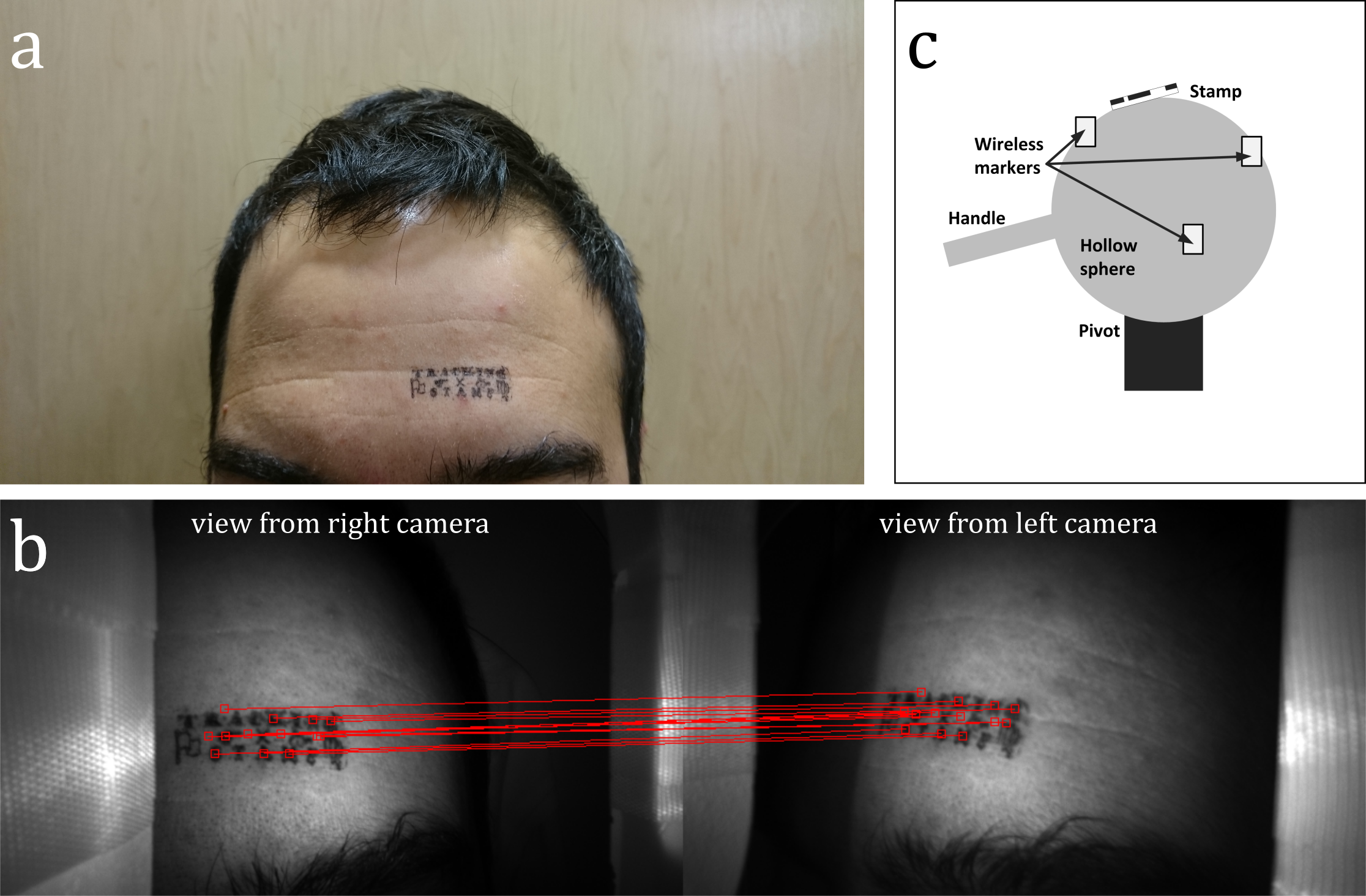
Tracking software and stamp: The pose-estimation method previously described by Kyme et al. (8) was adapted for this work. The method detects matching ‘features’ in the field of views of both cameras; these features are then used for tracking. A small stamp (Figure 2) was applied in both the phantom and in vivo experiments to ensure that consistent, and sufficient, features would be detected in both cases.
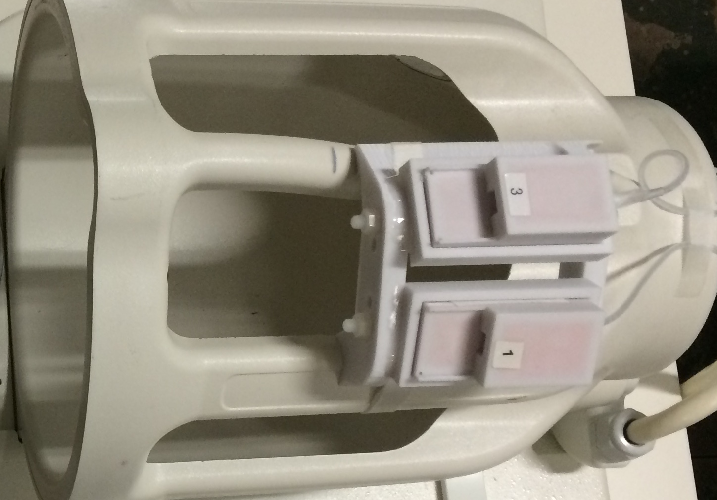
Phantom experiment: We constructed a phantom (Figure 2c) that could be tracked by the MR scanner (wireless active markers (9)) and by the camera system (the stamp on a small piece of paper glued to the surface of the phantom). The phantom was used for two purposes: 1) collecting cross-calibration data and 2) for a validation experiment to compare markerless tracking against the ground truth provided by the active markers.
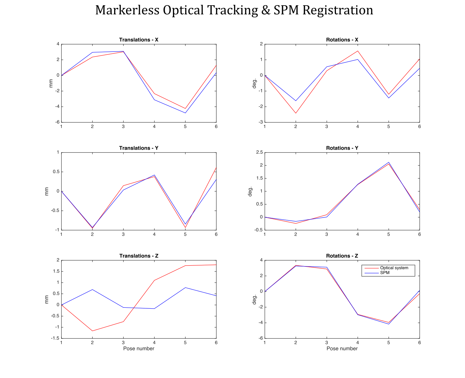
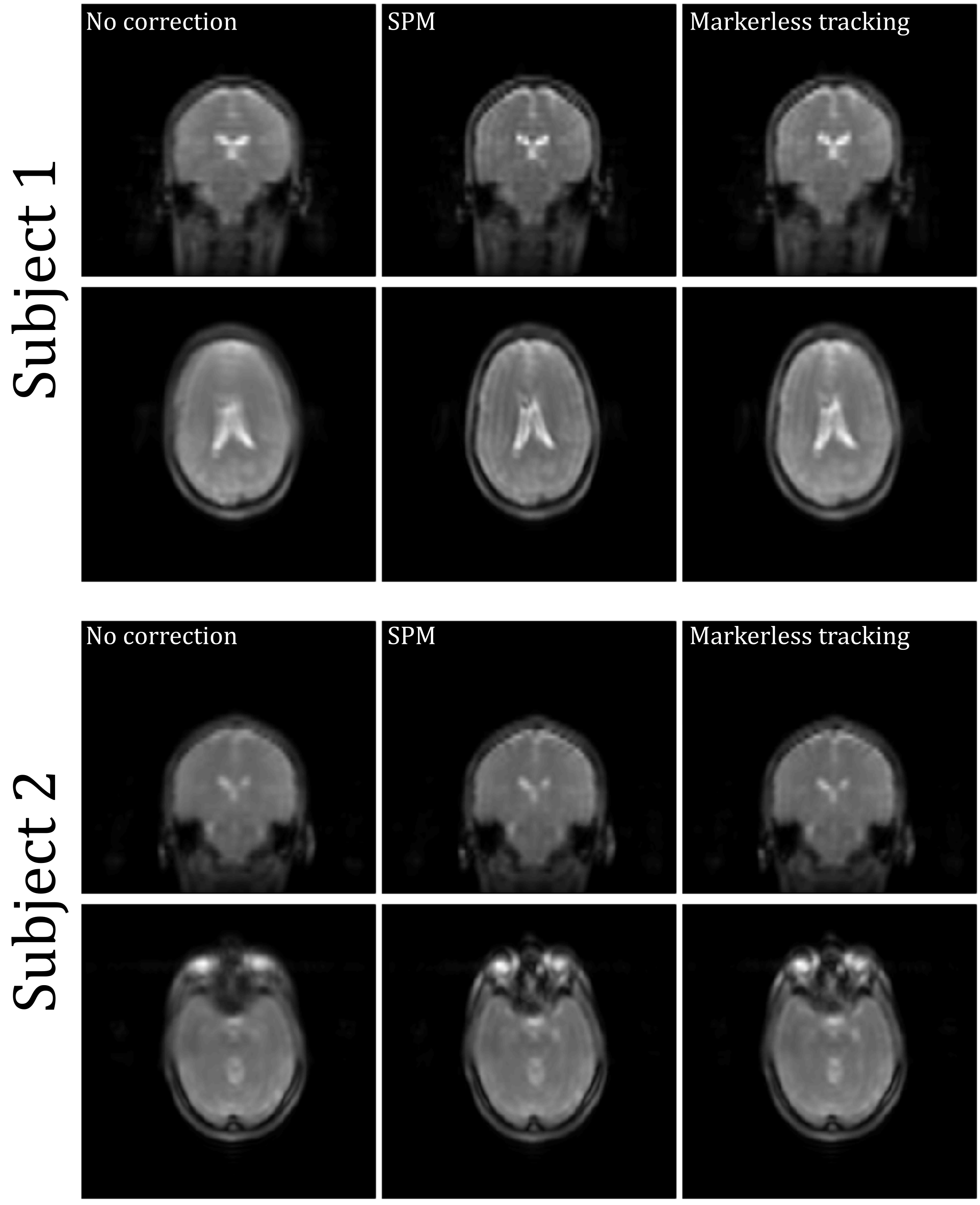
In vivo experiments: Two volunteers were scanned on a GE MR750 3T MR system and instructed to move their head between 6 poses. At each pose, each volunteer was imaged using a short 3D FSPGR scan (TE: 1.5s, TR: 4.9s. acq. time: 45 s). Data were processed twice: 1) The 6 volumes were retrospectively aligned in SPM and the 6-DOF motion parameters obtained this way were compared with poses obtained from the markerless tracking system. 2) the markerless poses were themselves used for retrospective realignment of the 3D FSPGR volume and the mean of the 6 volumes was obtained. This average volume was compared to the average volume obtained by SPM realignment and to the one obtained without realignment.
Results
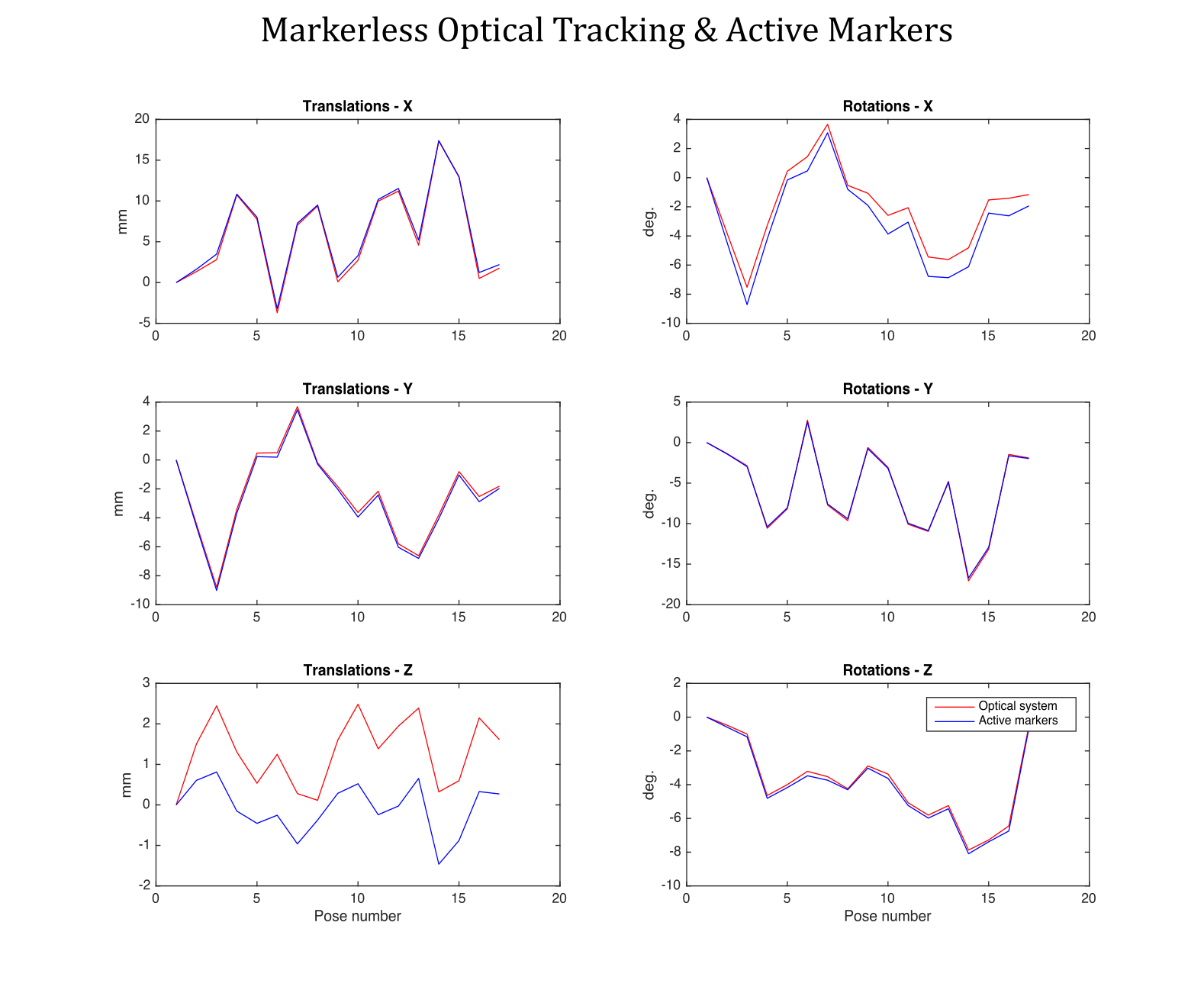
Figures 3 and 4 show phantom and in vivo tracking results, respectively. Figure 5 shows the result of using the markerless tracking data for registration of the navigator volumes for both Subjects 1 and 2. Registration quality using the markerless tracking data appears similar to registration using SPM.Discussion
In this work, we aimed to evaluate the feasibility of in-bore motion tracking of the head, using a feature detection approach, and coil and camera hardware already available at our institution. Results indicate that this approach can provide in vivo pose estimates suitable for motion correction. The advantage of this approach over other methods, such as structured light (9), is the smaller field-of-view required for accurate tracking, which is better suited for use in enclosed head coils.
We used a stamp on the skin to ensure that sufficient features were available for tracking. Ideally, this would be unnecessary, since the goal is seamless motion correction that requires no input from the technologist or patient. Future work should therefore explore the use of different feature detectors or lighting schemes (e.g. UV, IR) to best highlight natural features. A real-time implementation will also be essential for prospective motion correction for MR, although not for PET, where motion data can be included in the reconstruction.
Conclusion
Results show that head motion tracking with a view of only a small patch of skin is possible in the MR environment.Acknowledgements
NIH (2R01 EB002711 , 5R01 EB008706, 5R01 EB011654), the Center of Advanced MR Technology at Stanford (P41 RR009784), Lucas Foundation.References
1. Zaitsev M, Dold C, Sakas G, Hennig J, Speck O. Magnetic resonance imaging of freely moving objects: prospective real-time motion correction using an external optical motion tracking system. Neuroimage [Internet] 2006;31:1038–1050.
2. Qin L, van Gelderen P, Derbyshire JA, Jin F, Lee J, de Zwart JA, Tao Y, Duyn JH. Prospective head-movement correction for high-resolution MRI using an in-bore optical tracking system. Magn Reson Med [Internet] 2009;62:924–934. doi: 10.1002/mrm.22076 [doi].
3. Aksoy M, Forman C, Straka M, Skare S, Holdsworth S, Hornegger J, Bammer R. Real-time optical motion correction for diffusion tensor imaging. Magn. Reson. Med. [Internet] 2011;66:366–378. doi: 10.1002/mrm.22787.
4. Schulz J, Siegert T, Reimer E, Labadie C, Maclaren J, Herbst M, Zaitsev M, Turner R. An embedded optical tracking system for motion-corrected magnetic resonance imaging at 7T. Magn. Reson. Mater. Physics, Biol. Med. [Internet] 2012:1–11. doi: 10.1007/s10334-012-0320-0.
5. Maclaren J, Armstrong BSR, Barrows RT, et al. Measurement and Correction of Microscopic Head Motion during Magnetic Resonance Imaging of the Brain. PLoS One [Internet] 2012;7. doi: ARTN e48088DOI 10.1371/journal.pone.0048088.
6. Maclaren J, Herbst M, Speck O, Zaitsev M. Prospective motion correction in brain imaging: A review. Magn Reson Med [Internet] 2013;69:621–636. doi: 10.1002/mrm.24314.
7. Bouguet J-Y. Complete Camera Calibration Toolbox for Matlab. Jean-Yves Bouguet’s Homepage [Internet] 1999.
8. Kyme A, Se S, Meikle S, Angelis G, Ryder W, Popovic K, Yatigammana D, Fulton R. Markerless motion tracking of awake animals in positron emission tomography. IEEE Trans. Med. Imaging [Internet] 2014;33:2180–90. doi: 10.1109/TMI.2014.2332821.
9. Ooi MB, Aksoy M, MacLaren J, Watkins RD, Bammer R. Prospective motion correction using inductively coupled wireless RF coils. Magn. Reson. Med. 2013;70:639–647. doi: 10.1002/mrm.24845.
10. Olesen OV, Paulsen RR, Højgaard L, Roed B, Larsen R. Motion tracking for medical imaging: A nonvisible structured light tracking approach. IEEE Trans. Med. Imaging 2012;31:79–87. doi: 10.1109/TMI.2011.2165157.
Figures