1286
Motion-Correction Testing with an Anthropomorphic Brain Phantom1Department of Electrical Engineering, University of Hawaii at Manoa, Honolulu, HI, United States, 2Department of Medicine, John A. Burns School of Medicine, University of Hawaii, Honolulu, HI, United States
Synopsis
Motion-correction (MoCo) techniques enable clinicians to obtain high-quality MR images with decreased artifact from patient movement. MoCo methods can be tested on a phantom, but it is difficult to fully observe the benefits of MoCo on a simple phantom. In this study, we propose an anthropomorphic brain phantom with white matter and gray matter structure to work with a pneumatic motion simulator and demonstrate a practical application in a simulated motion study.
INTRODUCTION
Motion-correction (MoCo) techniques enable clinicians to obtain high-quality MR images with decreased artifact from patient movement. MoCo methods can be tested on a phantom, but it is difficult to fully observe the benefits of MoCo on a simple phantom. In this study, we propose an anthropomorphic phantom with white matter (WM) and gray matter (GM) structure to work with a pneumatic motion simulator and demonstrate a practical application in a simulated motion study.METHODS
A structurally anthropomorphic brain phantom was constructed from a FreeSurfer averaged brain surfaces1, 2 using a dual extrusion Makergear M2 (MakerGear LLC, Beachwood, Ohio, USA). The WM and GM surfaces were printed in 1.3 mm shells separated into four pieces. Polylactic acid (PLA) was used for the main structure and polyvinyl alcohol (PVA) was used as a water-soluble supporting structure. The combination of PLA and PVA minimized disparities in extrusion temperatures (~20 Cº) and allowed more precise printing. The 3D printed brain model was soaked in water overnight to dissolve the supporting materials. The total printing time of the brain was approximately 48 hours. A head model was created using FaceGen Modeler (Singular Inversions Inc., Toronto, ON, Canada) and printed with acrylonitrile butadiene styrene (ABS) with a 3 mm wall thickness. Two plastic screws were drilled into the ears to be used as a mount for the motion simulator. The total printing time of the head was approximately 22 hours. The agar gel for the WM and GM compartments were prepared to match T1 of the human brain with the recipe in literature3 and injected into WM and GM layers without making air bubbles. The cerebrospinal compartment was filled with low-conductivity water. All models were sprayed with enamel and the head was sealed with laser-cut acrylic after assembly to avoid leakage.
All the MRI data was acquired on a 3 T whole-body Tim TRIO MR scanner (Siemens Healthcare, Erlangen, Germany) with a 12-element head matrix coil. A whole-brain MPRAGE volume was acquired with a 1x1x1 mm voxel size with TI/TE/TR/flip/bandwith/Tacq=1400ms/4.15ms/3200ms/9º/130Hz/pix/12min23sec, a 256x256 encoding matrix and 192 partitions, with online image reconstruction. We did not use any acceleration techniques to avoid any potential artifact. Motion-tracking and correction were done using a camera and XPACE system4.
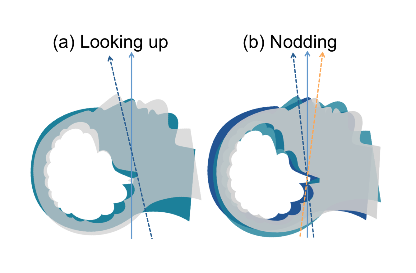
Two different movements were created with the motion simulator (Figure.1). A total of six MPRAGE scans (MoCo disabled) were acquired. Using a sphere phantom and the brain phantom, scans were initially taken without movement. Then two scans were repeated during movement (a), MoCo was then enabled and the brain phantom was scanned twice more; stationary and subjected to movement (b). The XPACE position lock was enabled and the center of k-space was equivalent for the two scans thus no image registration was required when subtracting two volumes for comparison. All movement was induced during the middle of MPRAGE scan (6min 23sec).
RESULTS
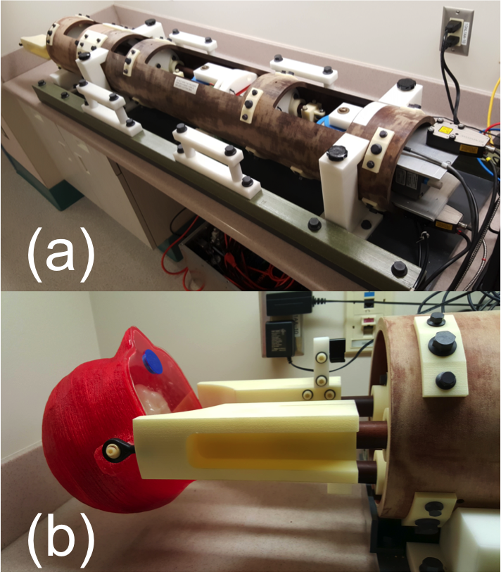
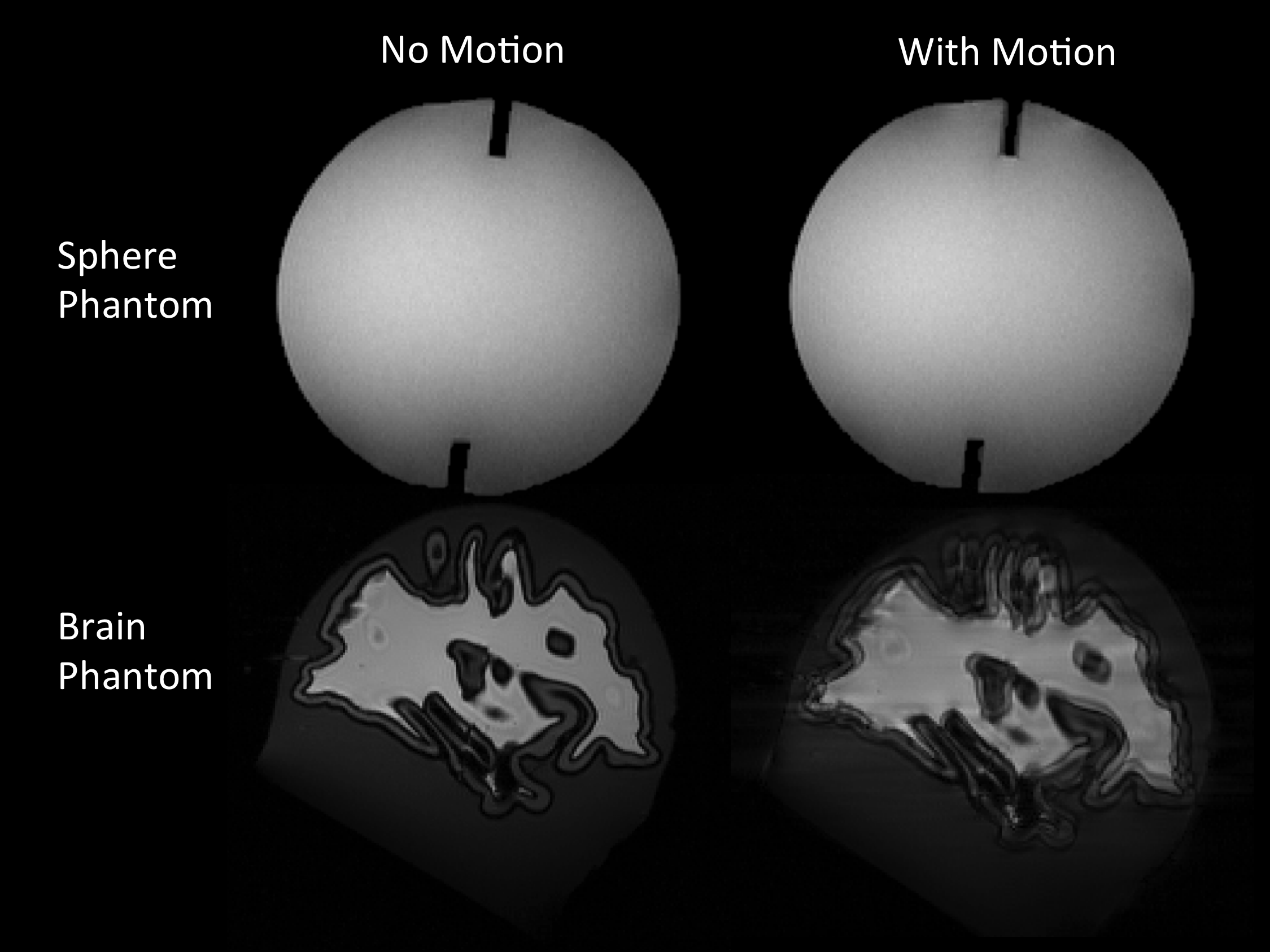
The phantom was successfully printed, assembled, and attached to the motion simulator (Figure 2). The sphere phantom images showed very small differences between scans acquired with and without motion (Figure 3(a)). The corners of the rectangular structure inside of the sphere phantom appeared slightly blurry in the image with motion. The brain phantom showed a significant difference between scans with and without motion (Figure 3(b)). The high structural complexity portions of the brain phantom, especially the intricate folding patterns, demonstrated the effects of the induced movements. The direction of movement was clearly visible in the brain phantom scan.
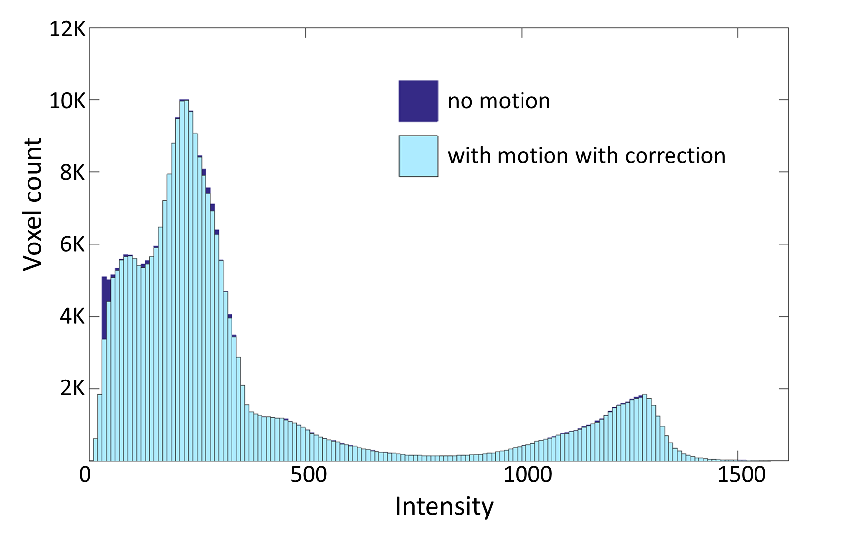
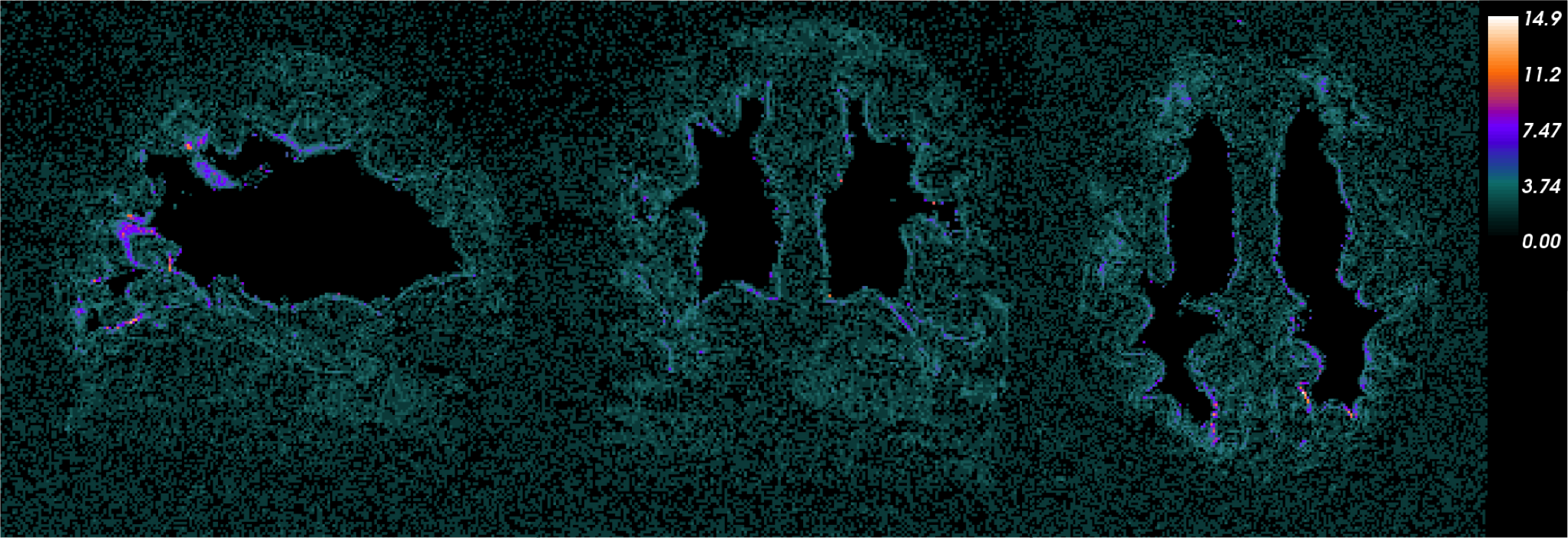
A small nodding movement did not create any distinct motion artifacts in the brain phantom images. However, when comparing scans with and without movement with MoCo enabled by taking the difference of the volumes, there were small volume differences (Figure 4). Fewer total voxels were observed in the resulting image of the motion-corrected scan. The voxel-by-voxel subtraction (Figure 5) shows more differences along the complicated folding pattern at the GM and WM boundaries.
DISCUSSION
The volume without motion had a slightly wider histogram distribution compared to the one with motion and MoCo enabled. The difference was very subtle but aligns with previous studies5, 6 that the estimated depth of cortical thickness can be lower with motion. The effect of motion was more apparent on the back of the head and in areas of the brain with complicated folding patterns.CONCLUSION
We demonstrated that the use of an anthropomorphic phantom helps localization of motion artifacts. Having detailed results from motion testing help MR researchers improve new MoCo methods and techniques efficiently.Acknowledgements
Grant
# R01DA019912, R01EB011517, K02DA020569, D-OE0000394.
References
1. Mathur-De Vre R, Grimee R, Parmentier F, Binet J. The use of agar gel as a basic reference material for calibrating relaxation times and imaging parameters. Magn. Reson. Med. 1985;2:176–179.3.
2. Dale A, Sereno M, and Fischl B. Cortical surface-based analysis. I. Segmentation and surface reconstruction. Neuroimage 1999; 9(2):179-194, 1999.
3. Fischl B, Sereno M, and Dale A. Cortical surface-based analysis II. Inflation, Flattening, and a Surface-Based Coordinate System. Neuroimage 1999;207:195-207.
4. Zaitsev M, Dold C, Sakas G, Hennig J, and Speck O, Magnetic resonance imaging of freely moving objects: prospective real-time motion correction using an external optical motion tracking system. Neuroimage 2006; 31:1038-1050.
5. Reuter M, Tisdall MD, Qureshi A, Buckner RL, van der Kouwe AJ, and Fischl B. Head motion during mri acquisition reduces gray matter volume and thickness Estimates. Neuroimage 2015; 107:107-115.
6. Tisdal MD, Reuter M, Qureshi A, Buckner RL, Fischl B, and van der Kouwe AJ. Prospective motion correction with volumetric navigators (vnavs) reduces the bias and variance in brain morphometry induced by subject motion. NeuroImage 2016;127:11-22.
Figures