1225
31-Channel brain array for hyperpolarized 13C imaging at 3T1Massachusetts General Hospital, A.A Martinos Center for Biomedical Imaging, Dept. of Radiology, Charlestown, MA, United States, 2Radiology and Biomedical Imaging, UCSF School of Medicine, San Francisco, CA, United States, 3Harvard Medical school, Boston, MA, United States
Synopsis
We describe the design and the performance of an integrated RF Tx and Rx coil to enable highly accelerated 13C imaging of the human brain at 3T. This system combines a 31-channel receive array with integrated preamps and a high-power transmit coil in an improved mechanical design, overcoming several longstanding design challenges that previously limited hyperpolarized 13C imaging. The shorter imaging times and more uniform spatial coverage attainable with our design will lead to a substantially increase in the range of hyperpolarized imaging applications, and enable the transition to clinical use.
Introduction
Hyperpolarized carbon-13 techniques for human clinical studies greatly benefit from sensitive receive arrays and highly accelerated parallel imaging strategies and Compressed Sensing [1] to mitigate rapid signal depletion during excitation [2]. We developed a 31-channel receive array with integrated preamps and a high-power transmit coil in an improved mechanical design for human imaging on a clinical 3T scanner. Combined, it overcomes several longstanding design challenges that previously limited hyperpolarized 13C MR imaging.Methods
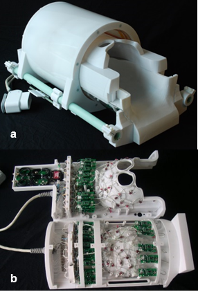
To make the helmet easily accessible to the subject, the volume coil and top half of the receive array slide forward (into the bore direction) as shown in Fig. 1a. When the subject's head is in the bottom half of the helmet, the top half and volume coil are then slid forward into place around the subject's head, and imaging can proceed. This single tuned carbon 31-channel receive array (Fig. 1b), uses the body coil for proton imaging , requiring additional protection diodes in front of the low impedance preamplifiers. It has 15 elements on the top half (with a diameter of 8.5 cm) and 16 on the bottom half (with a diameter of 9.5 cm) made of 16 AWG wire loops [3] with four or five evenly-spaced capacitors. All elements are tuned to 32 MHz and matched to a loaded impedance of 50 Ω to minimize the noise figure of the preamplifiers. Preamp decoupling is achieved with a cable length of 14 cm, with the preamps placed at a distance from the coil elements and as cable currents were not considered to be an issue with the low frequency of 32 Mhz. The active detuning circuit is formed across the match capacitor using an inductor and PIN diode. A detunable volume transmit coil (low-pass birdcage, diameter 30.5 cm, and a length of 30 cm to provide transmit efficiency across the A-P axis of the brain aligned in z) was built for excitation; high-power chokes were also used to enable high voltage pulses.
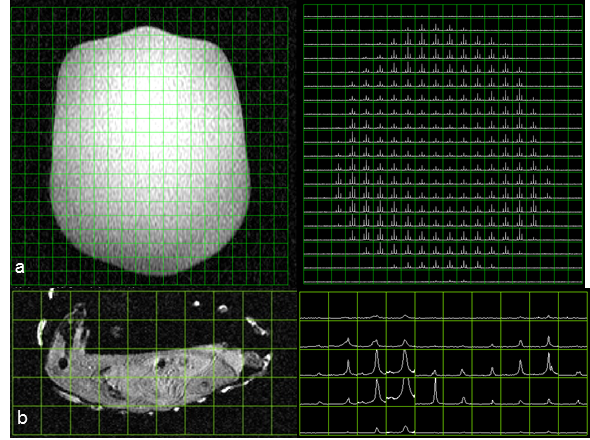
Data was acquired on a clinical 3T whole-body GE MR750 MRI scanner with 32 channel MNS receive. For T1-weighted 13C images (32x32 matrix, FOV= 24x24, TR= 500ms, Flip Angle= 53º) were obtained. The coil covariance matrix was calculated from the noise data that was obtained with and without RF excitation using an ethylene glycol head phantom (natural abundance 13C). The B1+ map was acquired using the Double Angle Method (32x32 matrix, FOV= 32x32 cm, TR= 3.0s, Flip angles [30º, 60º], Slice Thickness= 100mm) using the same phantom to determine B1 homogeneity of the volume transmit coil. 2D spectral data set were also acquired on the phantom (Fig 3a: 5cm thick slice with 20x20 phase encodes and 90o flip angle) and for a rat (Fig 3b: 2x2x2 cm3 using dynamic CSI with 10o flip angle, 10x10 phase encodes and 3 second time resolution).
Results
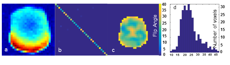
Each element shows a Q unloaded-to-loaded (with a human head) ratio of ~310/120. S21, loaded, between neighboring elements ranges from -18 dB to -12.5 dB. S11 reflections showed the elements tuned and matched to 50 ohms. Fig. 2a shows a T1-weighted 13C image which shows the relative SNR of the 13C peak from the ethylene glycol phantom, combined using sum of the squares from all of the channels. Fig. 2b shows the noise covariance matrix for the 31-channel carbon array indicating that all channels are functioning properly before and after 1H imaging. The B1+ map in Fig 2c shows relatively uniform transmit efficiency over the entire phantom. Fig. 2d shows the histogram of measured flip angles over the slice. The mean flip angle of 25º is slightly lower than the nominal flip angle of 30º. Fig. 3a shows a large spectral 2D data set showing excellent coverage with the expected signal gain. Fig. 3b shows a single time point from the dynamic CSI acquisition on a rat, in which the spatially variable pyruvate peak can be observed.Conclusions
The current system incorporates an improved mechanical design, preamps mounted at the coil detectors, and a transmit coil design capable of producing high-power pulses. This provides the requisite hardware to acquire high quality, accelerated 13C human images.Acknowledgements
This work was supported by NIH R01EB009756 and P41EB013598.References
[1] Ohliger et al. (2013) JMRI 38(3):701-13. [2] Wosik et al. (2015) Proc ISMRM [3] Wiggins et al. (2006) MRM 56:216-23Figures