1221
Receive Coil Array Considerations for Simultaneous Multislice Imaging in Cardiac MRI1Institute of Medical Physics and Radiation Protection, Department of Life Science Engineering, Mittelhessen University of Applied Sciences (THM), Giessen, Germany, 2A.A. Martinos Center for Biomedical Imaging, Department of Radiology, Massachusetts General Hospital, Harvard Medical School, Boston, MA, United States, 3Philipps University of Marburg, Department of Diagnostic and Interventional Radiology, Marburg, Germany
Synopsis
Receiver coil array simulation within realistic constrains are helpful for decision-making in coil design, especially when the array comprises many surface coil elements. Three coil array arrangements utilizing 64 loop elements were systematically evaluated regarding their encoding capabilities for accelerated simultaneous multi-slice cardiac acquisitions. Loop arrays consisting of small loop element near target region, but large once beyond the heart, seems to be best-suited for highly accelerated cardiac MRI.
Introduction
MRI is
playing an increasingly important role in the evaluation of cardiovascular diseases
and it is now routinely used in clinical diagnostic settings. In cardiac
magnetic resonance (CMR), both spatial and temporal resolved images of the
cardiac cycle must be acquired in a reasonable time frame in order to comply
with the patient’s ability to be successfully scanned. Therefore, in CMR, parallel
acquisition has impacted clinical applications such that nearly every cardiac
examination is performed with an array comprising multiple surface coil
elements. Recently developed multiband (MB), aka simultaneous multi-slice (SMS),
acquisitions1,2 are very appealing to CMR3,4, since they
share the SNR benefits of 3D sampling that arise due to Fourier averaging. The
burden of image encoding in regular in-plane parallel accelerated acquisition schemes
(e.g. SENSE, GRAPPA) is shared between the gradient coil and the receive array.
However, using SMS acquisitions, the simultaneous excited spins have to be
separated into individual MR slices using the encoding capabilities of the coil
array only. Thus, in SMS acquisitions, the receiver array can be considered as
the primary image
encoder.
Recent state-of-the-art MRI scanners utilize 64
channels and can therefore provide the ability to translate latest research in
coil technology to clinical cardiac MRI studies5. Here, we analyzed,
whether different cardiac coil arrays consisting of 64 channels can be
optimized for SMS encoding performances using a full wave simulation approach.
Methods
To asses encoding performance systematically, coil array simulations were carried out within the constraints of realistic coil former geometries. A semi-adjustability cardiac coil former (Fig.1), that we have developed previously5, is used for implementing three different array configurations (Fig.2): Coil A) 64-channel, diameter: 90 mm, overlapped design, symmetrically distributed. Coil B) 64-channel, diameter: 70 mm, gapped array, symmetrically distributed. Coil C) 64-channel, overlapped design; loop density variation (diameters: 50-130 mm), where smaller elements are centered over heart and larger elements around the target region6.Loop position and shape of the elements were directly 3D-modeled onto the coil former. Geometrical overlap was obtained from test loops bench measurements. We used the fast EM solver MARIE7,8 to simulate acceleration capabilities of the different array arrangements. The simulation included a conductive dielectric load (σ = 0.71 S/m, εr = 63.8) using a meshed torso model. Excitation was emulated using a sinusoidal unit current at the Larmor frequency of 123 MHz. The complex reception profile of the coil was taken as the B1- component of the simulated field in the transverse plane. In addition, we calculated each array’s mutual noise resistance matrix from the inner product of the spatially varying electric fields of the coils over the sample volume.
Accelerated noise amplifications were calculated for SMS using multiband accelerations factors of MB=4, MB=6, and MB=8 around the target region (Fig.3). In addition, we evaluated the array’s combined encoding capabilities using an in-plane acceleration factor of RSENSE=2, while emulating again multiple slice accelerations bands (MB=4;6;8).
Results
All designed array coils preformed quite equally using multiband accelerations of MB=4 (no in-plane acceleration; R=1) (Fig.4). Slice accelerations of MB=6 showed that the gapped array (Coil B) outperforms the symmetrical overlapped coil layout (Coil A). The coil arrangement with loop density variation (Coil C) showed lowest noise amplification. Similar coil ranking can be seen at multiband accelerations of MB=8, where the overlapped and gapped array exhibit g-factors up to 2.1, while the array configuration of Coil C shows only g-factors up of 1.5. Coil C also outperformed Coil A and B when combining SMS acquisition techniques with regular parallel imaging (e.g. 15% lower average g-factor by MB=8 and R=2). Figure 5 shows a close-up of the inverted g-factor map using a representative cardiac slice with the target ROI.Discussion
Receiver coil array simulation within realistic constrains are helpful for decision-making in coil design, especially when the array comprises a large channel count. Analyzing the three cardiac arrays showed, that the configuration with variation in the loop density (Coil C) provides the best encoding performance for CMR. This can be attributed to the smaller loop sizes close to the heart, which provide stronger spatial distinction of the sensitivity profiles in that target region. Thus, permitting a better separation of the simultaneously excited slices. Therefore, targeted designed arrays can be used for CMR acquisition with substantially reduced scan time.Conclusion
Three coil array arrangements utilizing 64 loop elements were systematically evaluated regarding their encoding capabilities for accelerated simultaneous multi-slice acquisitions. The array configuration that uses small loop element near target region, but large once beyond the heart, seems to be best-suited for highly accelerated CMR.Acknowledgements
No acknowledgement found.References
1. Setsompop K, Gagoski BA, Polimeni JR, et al. Blipped-Controlled Aliasing in Parallel Imaging (blipped-CAIPI) for Simultaneous Multislice EPI With Reduced g-Factor Penalty. Magn Reson Med. 2012;67:1210-1224.
2. Feinberg DA, Moeller S, Smith SM, et al. Multiplexed Echo Planar Imaging for Sub-Second Whole Brain FMRI and Fast Diffusion Imaging. PLoS ONE. 2010;5(12)
3. Mekkaoui C, Reese, TG, Jackowski MP, et al. Diffusion Tractography of the Entire Heart Using Free-Breathing Accelerated Simultaneous Multislice Imaging. In proc ISMRM. 2016;24:3111.
4. Lau AZ, Tunnicliffe EM, Frost R, et al. Accelerated Human Cardiac Diffusion Tensor Imaging Using Simultaneous Multislice Imaging. Magn Reson Med. 2015;73:995-1004.
5. Etzel R, Xueming C, Mekkaoui C, et al. Design Optimization and Evaluation of a 64-Channel Cardiac Array Coil at 3T. In proc ISMRM. 2015;23:1780.
6. King SB, Smith MJ, Matwiy J, et al. 31-Channel 3T Cardiac Array Optimized for SNR and g-Factor. In proc ISMRM. 2012;20:2647
7. Polimeridis AG, Villena JF, Daniel L, et al. Stable FFT-JVIE solvers for fast analysis of highly inhomogeneous dielectric objects. J Comput Phys. 2014;269:280-296.
8. Villena JF, Polimeridis AG, Wald LL, et al. MARIE – a MATLAB-based open source software for the fast electromagnetic analysis of MRI systems. In proc ISMRM. 2015;23:0709.
Figures
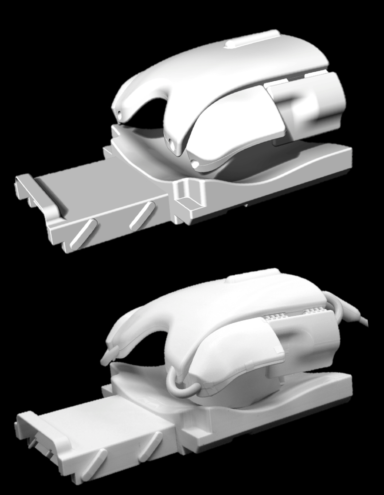
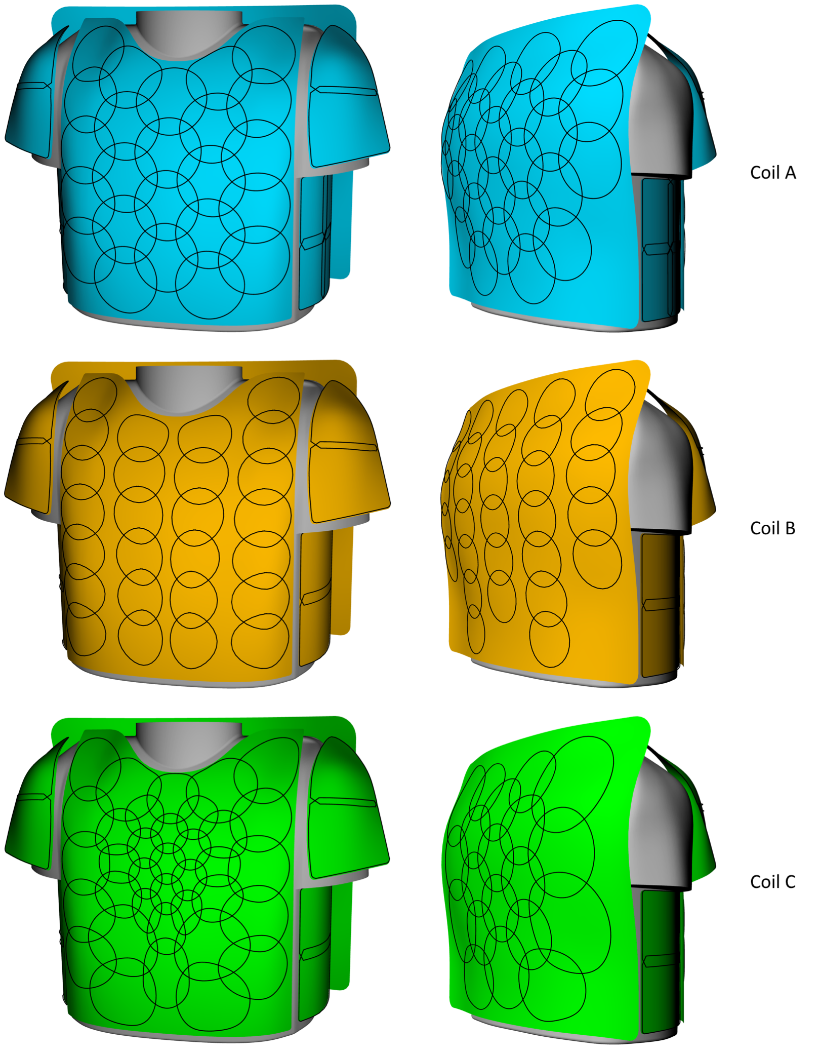
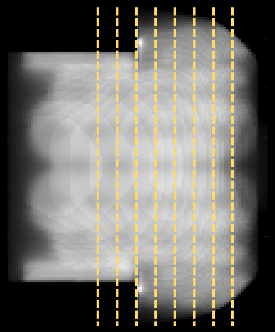
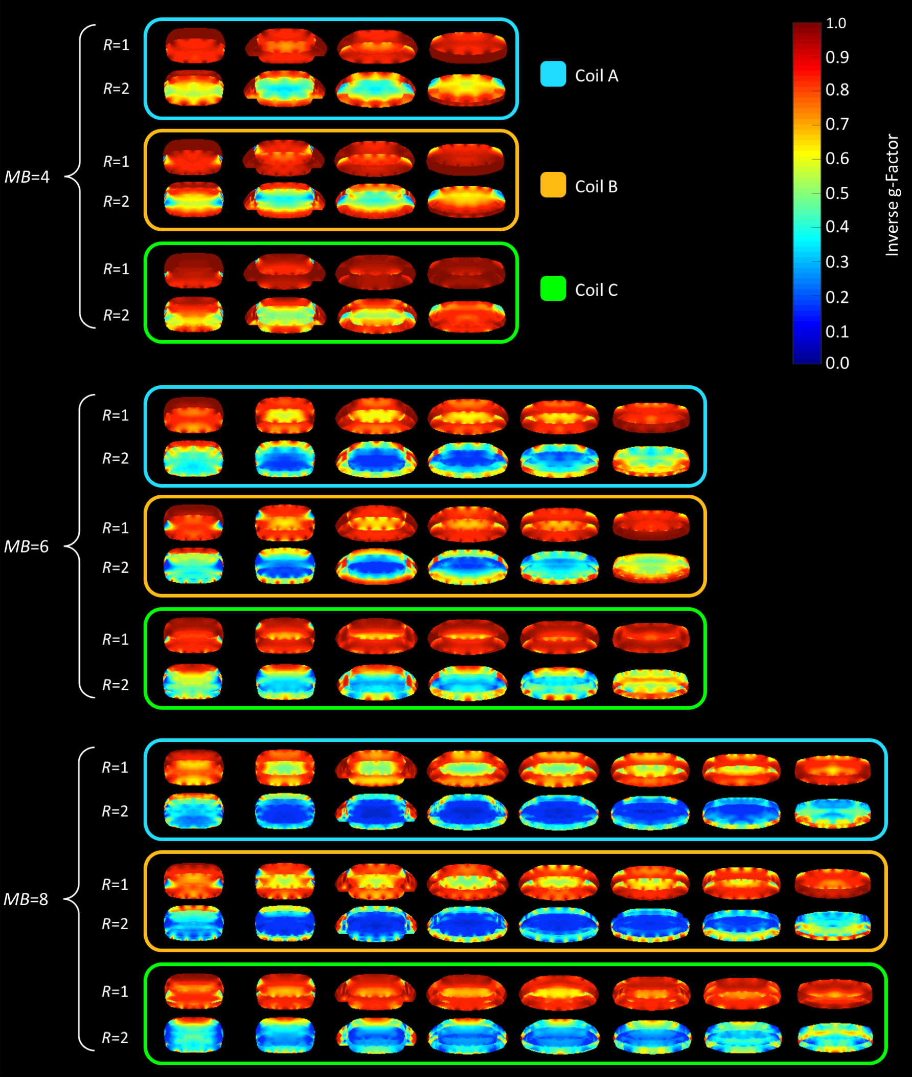
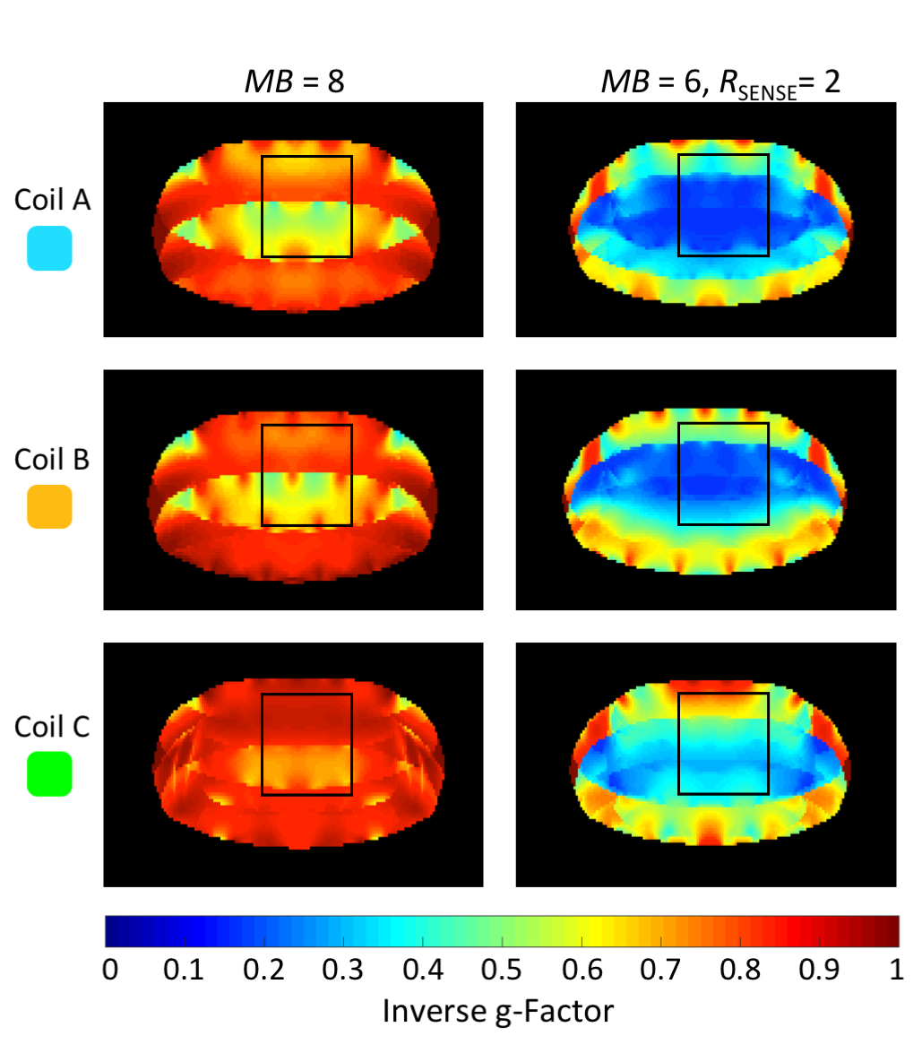
Figure 5: Inverse g-factor maps of a representative transverse slice with marked cardiac ROI. First column: MB=8, cardiac ROIs show average g-factors of 1.7, 1.5, and 1.1 for coil arrangement A, B, and C, respectively. Second column: MB=8 and R=2, average g-factors are measure to be 4.1, 3.8, and 3.1 for coil configuration A, B, and C, respectively.