1218
An integrated 32-channel transmit and 64-channel receive 7 tesla MRI system1Center for Magnetic Resonance Research, University of Minnesota, Minneapolis, MN, United States, 2Siemens Healthcare, Erlangen, Germany
Synopsis
At 7T, commercial MRI systems are currently available with a maximum of 8-16 transmit channels and 32 receive channels. To explore the potential benefits of increasing these numbers, which have been predicted by prior experimental and simulation work, we have developed and installed 32-channel RF transmitter and 64-channel receiver upgrades for a standard 7T commercial MRI system. These additions have been fully integrated into the system in a way that they can be reliably employed for routine studies without requiring significant workflow modifications or special user training.
Purpose
It is well understood that arrays of local transmit RF coils can be used in combination with “B1+ shimming” techniques to mitigate the inherent inhomogeneity of transmit B1 (B1+) fields at 7T, and to reduce RF power deposition (SAR)1,2. This has driven the availability of commercial 7T MRI systems with optional parallel transmitter upgrades of 8-16 channels for research. However, experimental and simulation results have shown that there are ample improvements to be realized by continuing to increase the number of available independently-controllable transmit channels3,4. To explore the potential of higher transmit channel counts at 7T, particularly for body applications and often SAR limited simultaneous multi-slice/multi-band imaging, we have developed and installed a robust 32-channel, 32 kW RF transmitter system.
Arrays of local receive RF coils are extremely useful for improving image quality and acquisition speed at high magnetic fields5,6. While commercial MRI systems are now available at 3T with up to 128 receive channels, at 7T and above the limit has heretofore been 32 channels. To explore the applications that can take advantage of the faster acquisitions and higher SNR achievable at 7T with higher receive coil counts, we have developed and implemented a 64-channel receiver system.
Methods
The system is based on a standard commercial MAGNETOM 7T (Siemens Healthcare, Erlangen, Germany), which is normally equipped with a single transmit channel and up to 32 receivers.
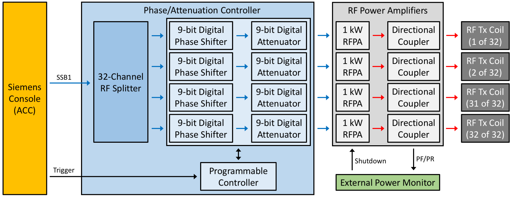
The transmitter system was expanded to 32 channels by adding a 32-channel phase/attenuation controller (CPC Amps, Hauppauge, NY, USA). This device effectively splits a single input 32 ways with digital control of the phase and attenuation of each channel (resolution: 0.7º, 0.125 dB per step). Phases and amplitudes for all channels can be changed in less than 1 μs, synchronized with scanner acquisition, allowing for dynamic B1+ shimming and spoke pulses. The modulated split signal is delivered to 32 independent 1 kW RF power amplifiers (CPC Amps, Hauppauge, NY, USA). A 64-channel power monitoring system is used to monitor the forward and reflected power of each channel and automatically shut down the system if excessive power is detected. A diagram of the transmit system is presented in Figure 1.
The receiver system was expanded to 64 channels by adding an additional cabinet in the equipment room containing receiver cassettes and splitters for the local oscillator and clock signals required for synchronization. A second 32-channel RF switch matrix was added at the service end of the magnet to provide power for preamplifiers and secondary gain. Similar modifications have been demonstrated at 3T7. For improved usability compared to previous implementations, a custom controller area network (CAN) device was developed and installed to automatically route the system CAN bus messages such that the component modifications are transparent to the operator. Digital receiver cards were added to the standard image reconstruction computer to receive the digitized signal, and software patches were implemented to support simultaneous acquisition with all receivers and to allow for the product adjustments and image reconstruction processes to function fully in real time with any combination of receivers active.
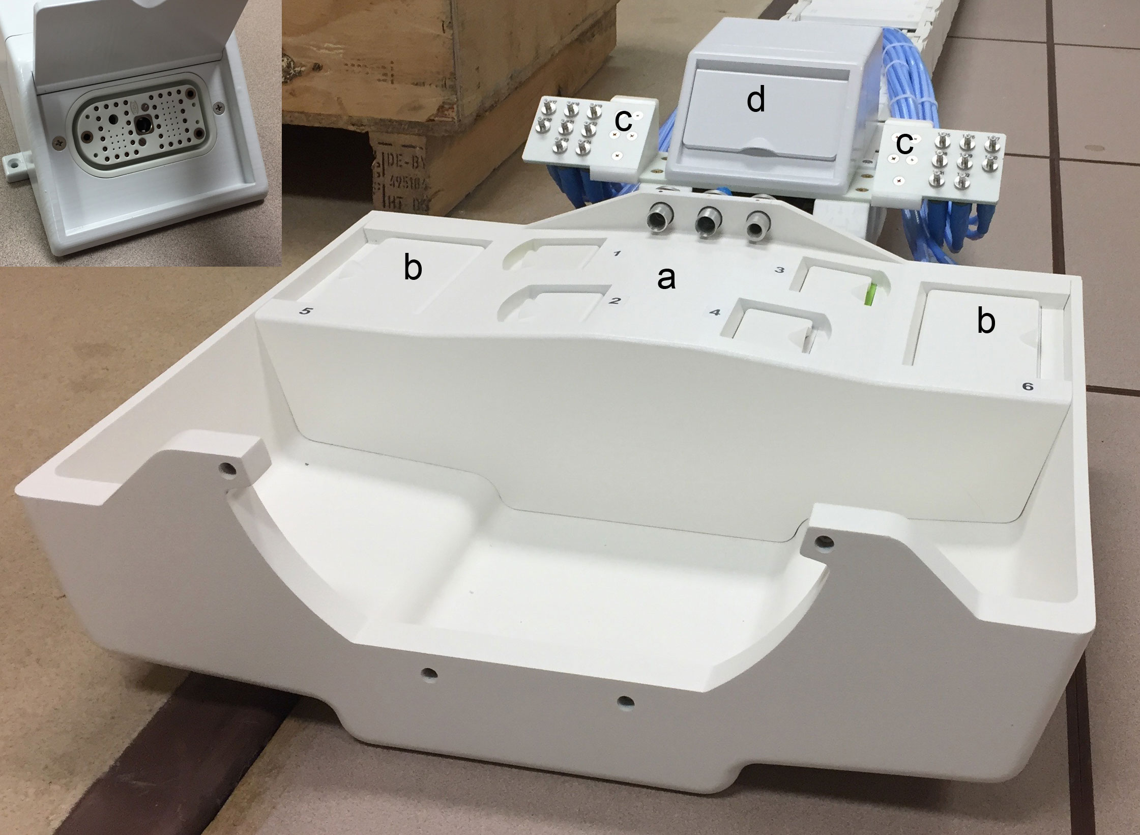
To manage the large number of cables
involved in this configuration in a practical way allowing the system to be
used routinely, the manufacturer's standard coil interface and cabling were
extensively modified, as pictured in Figure 2. To accommodate
the first 16 transmit and 32 receive channels, the standard coil interface was replaced with one normally used on
16-channel parallel transmit systems. Custom mounting hardware and RF
connectors were designed and installed for the added 16 transmit and 32 receive
channels. The standard RF infrastructure cabling was
modified and extended to provide 32 additional pin diode driver lines for
tuning coils and controlling T/R switches. To physically accommodate the
additional cabling, a larger reinforced cable
carrier was installed (igus, Cologne, Germany). The manufacturer's
standard transmit RF cabling was replaced with compact ultra-low-loss cable
(SUCOFLEX 106, Huber+Suhner, Herisau, Switzerland), reducing cable volume by
~40% while also reducing power losses due to cable attenuation by 0.33 dB.
Results & Conclusion
The system upgrades were validated by collecting phantom data using prototype coils.
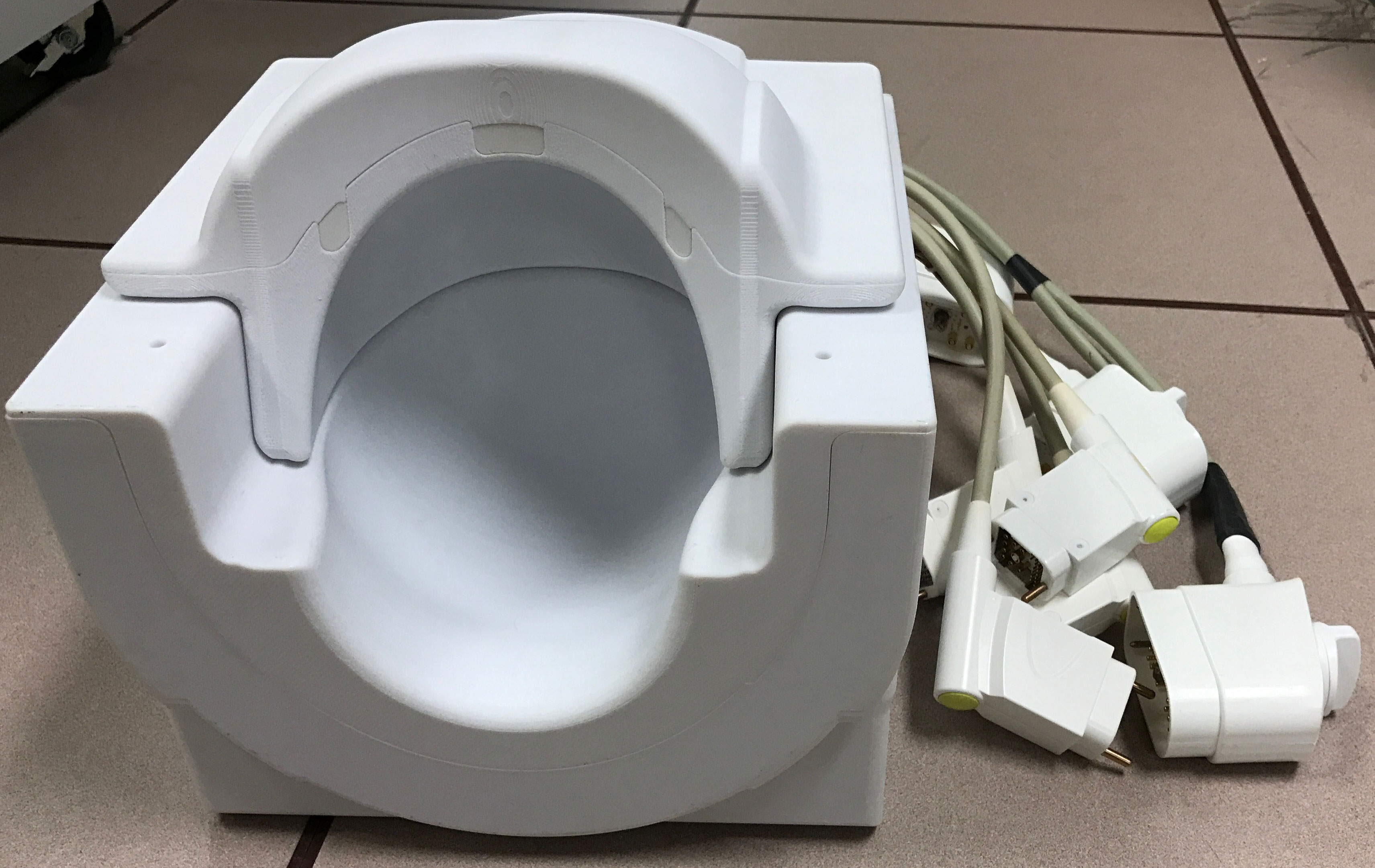
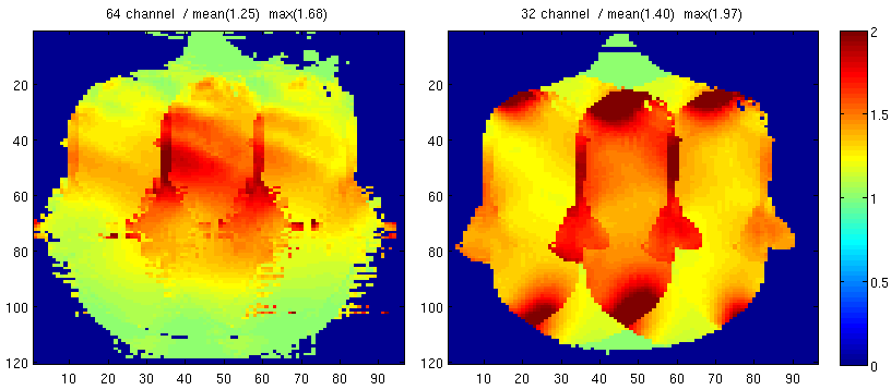
A 16-channel transmit/64-channel receive head coil is pictured in Figure 3. A comparison of g-factors for this coil vs. a standard 32-channel receive coil shows an expected improvement for parallel imaging (Figure 4).
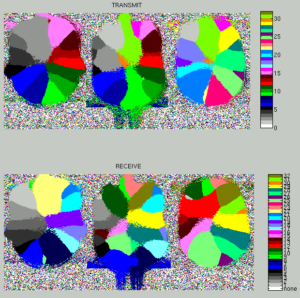
Coil contribution maps for a 32-channel transmit/32-channel receive head coil8 are presented in Figure 5.
Future work will explore the performance of the aforementioned coils in more detail, as well as investigating novel 32-channel transmit and 64-channel receive coils for head and body applications.
Acknowledgements
This work is supported by NIH grants P41 EB015894 and S10 RR026783, and the W. M. Keck Foundation.References
1. Van de Moortele PF, Akgun C, Adriany G, Moeller S, Ritter J, Collins CM, Smith MB, Vaughan JT, Ugurbil K. B(1) destructive interferences and spatial phase patterns at 7 T with a head transceiver array coil. Magn Reson Med. 2005 Dec;54(6):1503-18.
2. Zhu Y. Parallel excitation with an array of transmit coils. Magn Reson Med. 2004 Apr;51(4):775-84.
3. Adriany G, Gozubuyuk A, Auerbach E, Van de Moortele PF, Andersen PM, Vaughan JT, Ugurbil K. A 32 channel transmit/receive transmission line head array for 3D RF shimming. In: Proceedings of the 15th Annual Meeting of ISMRM, Berlin, Germany, 2007 (Abstract 166).
4. Mao W, Smith MB, Collins CM. Exploring the limits of RF shimming for high-field MRI of the human head. Magn Reson Med. 2006 Oct;56(4):918-22.
5. Wiggins GC, Polimeni JR, Potthast A, Schmitt M, Alagappan V, Wald LL. 96-Channel receive-only head coil for 3 Tesla: design optimization and evaluation. Magn Reson Med. 2009 Sep;62(3):754-62.
6. Keil B, Blau JN, Biber S, Hoecht P, Tountcheva V, Setsompop K, Triantafyllou C, Wald LL. A 64-channel 3T array coil for accelerated brain MRI. Magn Reson Med. 2013 Jul;70(1):248-58.
7. Potthast A, Kalnischkies B, Kwapil G, Wald LL, Heumann T, Helmecke S, Schor S, Pirkl G, Buettner M, Schmitt M, Mattauch G, Hamm M, Stransky P, Baumgartl R, Hebrank FX, Peyerl M. A MRI system with 128 seamlessly integrated receive channels. In: Proceedings of the 15th Annual Meeting of ISMRM, Berlin, Germany, 2007 (Abstract 246).
8. Adriany G, Schillak S, Waks M, Tramm B, Grant A, Yacoub E, Vaughan JT, Olman C, Schmitter S, Ugurbil K. A modular 16 ch. Transmit/32 ch. Receive Array for parallel Transmission and High Resolution fMRI at 7 Tesla. In: Proceedings of the 23rd Annual Meeting of ISMRM, Toronto, Ontario, Canada, 2015 (Abstract 622).
Figures