1217
Towards massively parallel multi-transmit for body imaging at 7 T1Division Imaging, Department of Radiology, University Medical Center Utrecht, Utrecht, Netherlands, 2Division Imaging, Department of Radiotherapy, University Medical Center Utrecht, Utrecht, Netherlands, 3Biomedical Image Analysis, Eindhoven University of Technology, Eindhoven, Netherlands
Synopsis
A simulation study was done to assess optimal transmit setups for massively parallel (up to 32 channels) transmit body imaging at 7
Purpose
Multi-transmit MRI has been a driving factor for advancement in ultrahigh-field imaging. Gaining control over phase and amplitude of individual transmit channels can be used to mitigate transmit field inhomogeneities, increase transmit efficiency and to decrease energy deposition1–3. Increasing the channel count has been demonstrated to improve transmit performance for body imaging when moving up to sixteen transmit channels4,5. It is hypothesized that a further increase in the number of transmit channels results in more control over the transmit field, leading to an enhancement of the transmit performance. A simulation-based exploratory study was carried out to investigate the performance of several massively parallel multitransmit setups, with a maximum channel count of 32. Prostate scans were carried out with a 24 channel transmit setup on a male volunteer.Methods
Finite difference time domain simulations (Sim4Life, Zurich Med tech, Zurich) were used to assess different antenna configurations for massively parallel transmit body imaging. Six different antenna setups were simulated on a phantom that mimics the electric properties of the pelvis (σ=0.4 S/m, e=34). Different antenna geometries (loop, small and large dipole, monopole) were tried, as well as different channel counts (8,16, 24 and 32 channels). Figure 1 shows the transmit configurations that were simulated. Simulations of the 24 channel small dipole array were carried out on human model Duke6. Within the limits of our current hardware, it was possible to increase the number of phase controlled transmit channels to 24. This was done by utilizing the current 8 channel multi-transmit system (Multix, Philips Healthcare, Best), an 8*1 kW amplifier connected to a vector modulator and a 1*4 kW amplifier fed into an 8 channel Butler matrix. The Peak power of this setup was measured on the coil-connection plane, with an average peak power of 250 W per channel. The 24 channel transmit setup was constructed and tested for prostate scans on a male volunteer. Informed consent was obtained following the protocols of our institutional review board. B1+-shimming was carried out on the prostate, after which survey scans and a AFI B1+-map were acquired.Results
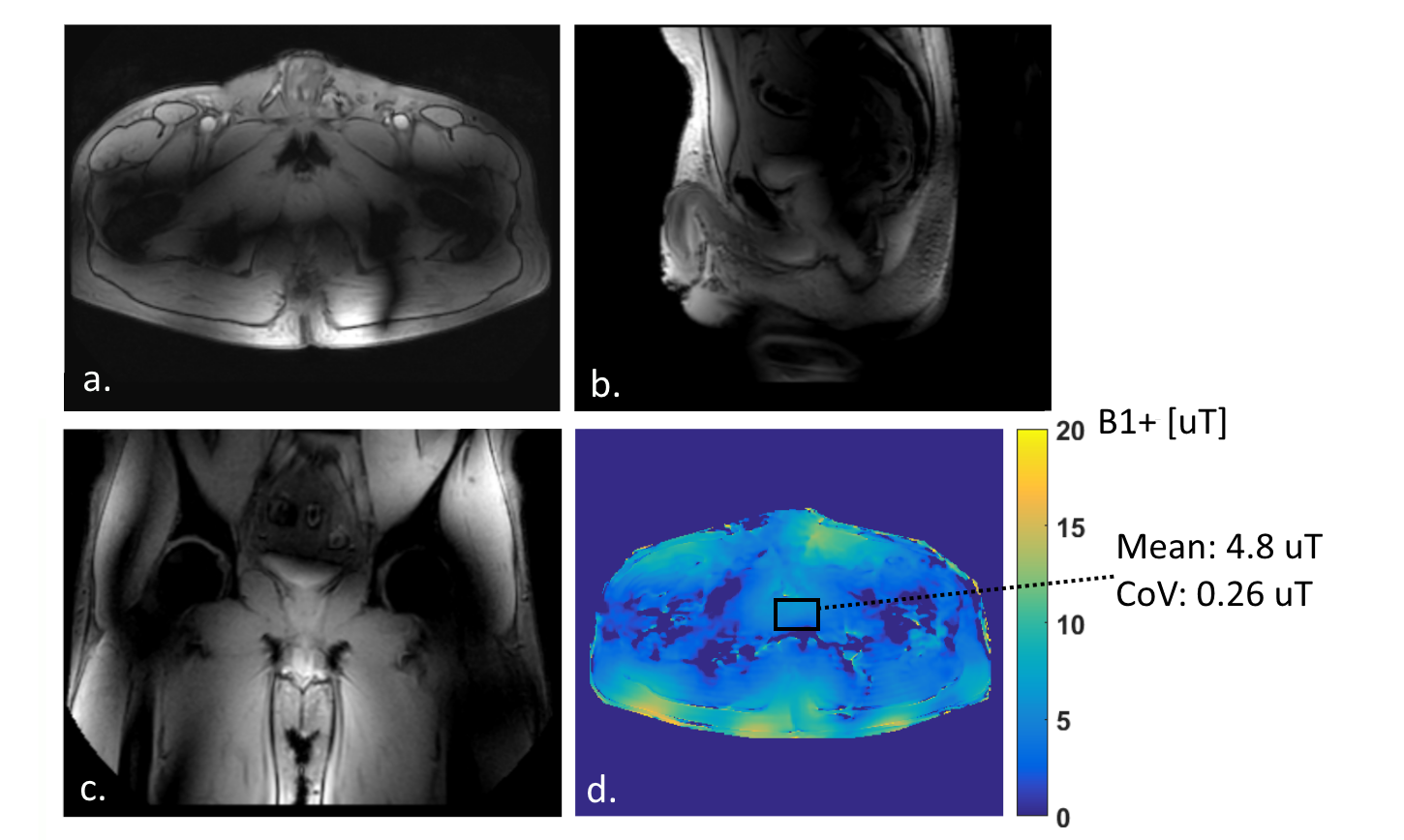
Figure 2 shows B1+/√SAR-distributions for different antenna configurations. Shimming was carried out on the elliptical region of interest in the phantom. Figure 3 summarizes the quantitative results of the phantom simulations. For dipoles, moving from 8 to 16 transmit channels does not provide clear benefits in terms of effective SAR (SAR/(B1+ )2). Increasing the channel count from 8 to 24 channels decreases effective SAR by 15%, increasing to 32 channels decreases effective SAR by 30%. The setups with the loops and the monopoles do not decrease effective SAR with respect to the 8 channel dipole setup. The 24 channel simulations on human model Duke (figure 4) show a maximum SAR10g of 6.8 W/kg for 24 W input power. This is a decrease of 23% with respect to the 8 channel fractionated dipole array7. These SAR levels lead to average power constraints of 1.47 W per channel. Figure 5 shows the results of the prostate scans. The surveys display a homogeneous signal throughout the pelvic region. The B1+-map shows that an average B1+ of 4.8 μT was obtained in the prostate.Discussion
A comparison of different transmit configurations on a phantom indicates that increasing the number of transmit channels increases transmit performance. Increasing the number of transmit channels from 8 to 32 provides a decrease of 30% in effective SAR. These performance benefits are demonstrated only when using small dipole antennas; monopole antennas or loop coils are not useful for massively parallel multitransmit. Simulation results on Duke indicate that a transmit efficiency of 0.35 μT/√W is obtained with a 24 channel dipole array. This transmit efficiency is not matched in the MRI experiments, possibly due to cable coupling effects or suboptimal phase control of the channels connected to the Butler matrix. Finally, the small dipole antennas that are simulated do not have enough length to be self-resonant, which forces the use of large inductors for matching. Inductor losses may have negative effects on the transmit efficiency. Alternative transmit setups in which loops and dipoles are combined will be included in this study for future work.Conclusion
Several transmit array designs have been investigated for their potential to improve transmit performance with an increased number of transmit channels. An array of 32 shorter dipole elements provides the best performance with 30% effective SAR reduction in comparison to the reference setup. A proof of principle experiment for this design has been provided with a 24 channel setup for prostate imaging on a volunteer.Acknowledgements
This work is part of a project funded by Dutch Technology Foundation STW, project number 13783References
1. Katscher U, Boernert P. Parallel RF transmission in MRI. NMR in Biomedicine. 2006;19(3):393–400.
2. Metzger GJ, Snyder C, Akgun C, Vaughan T, Ugurbil K, de Moortele V, others. Local B1+ shimming for prostate imaging with transceiver arrays at 7T based on subject-dependent transmit phase measurements. Magnetic Resonance in Medicine. 2008;59(2):396–409.
3. Padormo F, Beqiri A, Hajnal J V., Malik SJ. Parallel transmission for ultrahigh-field imaging. NMR in Biomedicine. 2016;29(9):1145–1161.
4. Ertürk MA, Raaijmakers AJE, Adriany G, Ugurbil K, Metzger GJ. A 16-channel combined loop-dipole transceiver array for 7 Tesla body MRI. Magnetic Resonance in Medicine. 2016;0:1–11.
5. Snyder CJ, DelaBarre L, Moeller S, Tian J, Akgun C, Van De Moortele P-F, Bolan PJ, Ugurbil K, Vaughan JT, Metzger GJ. Comparison Between Eight- and Sixteen-Channel TEM Transceive Arrays for Body Imaging at 7 Tesla. Magnetic Resonance in Medicine. 2012;67(4):954–964.
6. Kuster AC and WK and EGH and KH and MZ and EN and WR and RJ and WB and JC and BK and PS and H-PH and J. The Virtual Family—development of surface-based anatomical models of two adults and two children for dosimetric simulations. Physics in Medicine and Biology. 2010;55(2):N23.
7. Raaijmakers AJE, Italiaander M, Voogt IJ, Luijten PR, Hoogduin JM, Klomp DWJ, van den Berg CAT. The fractionated dipole antenna: A new antenna for body imaging at 7 Tesla. Magnetic Resonance in Medicine. 2015;0:1–9.
Figures