1176
Focus Correction in MR thermography for Precise Targeting in Focused Ultrasound Thalamotomy for Essential Tremor1Physics, Soochow University, Taipei, Taiwan, 2Radiology, Harvard Medical School, Brigham and Women’s Hospital, Boston, MA, United States, 3Biomedical Engineering, Shanghai Jiao Tong University, Shanghai, People's Republic of China
Synopsis
MRI-guided focused ultrasound thalamotomy has proved an effective method for the treatment of Essential Tremor. Precise alignment of the focus to the target in the thalamus is crucial. Proper targeting is complicated by artifactual shifts in hot spot location, with respect to anatomical images. We identified two sources of errors and proposed solutions to both; the correction scheme does not require any modification to the pulse sequence or imaging protocol. Shifts by 1.0±0.1 mm were detected and corrected, for three separate sonications in one given patient. The size of the shifts agreed with observations from the literature.
Purpose
Focused
Ultrasound (FUS) Surgery has proved an effective treatment for Essential Tremor
(ET)1. A thalamic target is ablated using FUS energy, under magnetic
resonance (MR) guidance. Accurate focusing of the FUS beam is crucial to the
success of the procedure, a difficult task given the small size of the targeted
structure. To achieve accurate targeting, a series of low acoustic power sonications
were delivered to progressively adjust the location of the focus. Image artifacts
may cause the focus to appear spatially displaced with respect to underlying
anatomical images, thus confusing the alignment process. In practice, because
errors predominantly occur in the frequency-encoding direction, this problem
can to some degree be circumvented by acquiring pairs of images with different
orientations for frequency encoding. Even though Fig. 1 shows a sizeable offset
between the focus (red spot) and the target (green rectangle), this offset was
in fact artefactual, and the two were maybe properly aligned. Our goal is to describe
and correct for these offsets, hopefully making the targeting process more
straightforward and intuitive. Methods
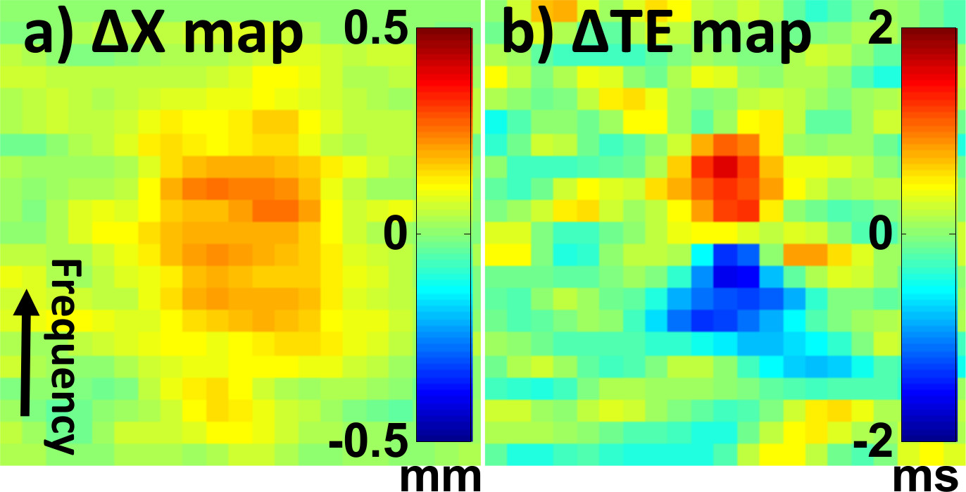
There are two main causes for the mentioned offsets, and methods are proposed here to compensate for both. One cause is the well-known ‘chemical shift’ artifact, whereby heated tissues have a different Larmor frequency and as a result will appear displaced in frequency direction. A second, less-recognized effect comes from spatial variations in Larmor frequency and the k-space shifts that result, causing temperature-measurement errors3. Given B0, a measured field map, spatial warping is required to correct for ‘chemical shift’ artifacts associated with B0. In a second step, pixel-by-pixel temperature corrections were applied to account for $$$ \frac{\partial B_{0}}{\partial x} $$$, which can affect the centroid location of the hot spot. With no field maps acquired in current protocol, phase-difference maps, or temporal changes of field maps, were used for Larmor frequency measurements. The TE errors were calculated:
$$ \triangle TE(\vec{r})=N_{f}\times\triangledown(\triangle \phi(\vec{r}))/BW/2\pi $$
where Nf is the matrix size in the frequency-encoding direction, $$$ \triangle \phi(\vec{r}) $$$ is the phase-difference map subtracted from baseline, $$$ \triangledown(\triangle \phi(\vec{r})) $$$ is the spatial gradient, and BW is the total receiver bandwidth. The corrected temperature map, $$$ T(\vec{r}) $$$, was obtained from the corrected echo time:
$$ TE(\vec{r})=TE+\triangle TE(\vec{r}) $$
Methods
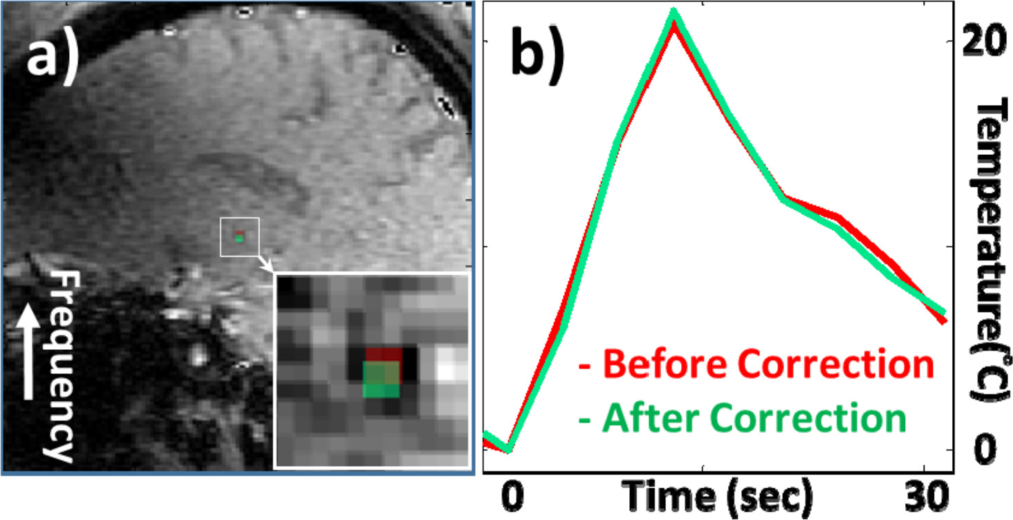
An ET patient was treated following informed consent, using an hemispheric, 650-kHz, 1024-element, phased-array transducer (ExAblate Neuro, InSightec, Israel), and a 3T GE MRI system for guidance (FOV=28×28cm2, TE/TR=12.9/27.8ms, matrix size =128×256 zero-filled to 256×256, BW = ±5.68kHz, 10 time frames). Details of the procedure were as described in Lipman et al2. Results from three separate sonications, with mean peak voxel temperature elevation of 22.9±3.5°C, were corrected here for spatial shifts.Results
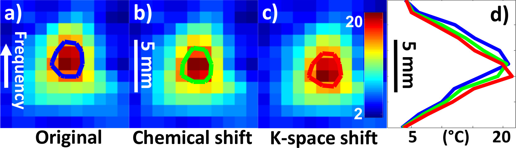
Results for chemical shift and k-space shift correction are shown in Fig. 2 and Fig. 3. In Fig. 2a, the Δx map shows the spatial shift for pixels in the T map, due to a ‘chemical shift’ effect. In Fig. 2b, the TE error map can be used to correct temperature values: Note the different polarity on either side of the profile, causing overestimation on one side and underestimation on the other. The temperature elevation map T around the hot spot is shown in Fig. 3 without correction (Fig. 3a), using only the Δx correction from Fig. 2a (Fig. 3b, centroid shifts by 0.56 mm), or using both corrections from Fig. 2 (Fig. 3c, 0.56 + 0.39 mm = 0.95 mm shift). The resulting spatial shifts can also be visualized in Fig. 3d. In Fig. 4a, T maps were overlaid onto the corresponding anatomical image, using red and green overlays for results without and with correction, respectively. As seen in Fig. 4b, spatial shifts did not appreciably affect temporal dynamics. In all three sonications analyzed here, the overall focus shift was 1.0 ± 0.1 mm, close to what was observed in clinical setting2 and in Fig. 1. Changing the ordering of the two corrections had negligible effect (< 1% here).Discussion
The well-known ‘chemical shift’ effect is not sufficient to account for hot spot shifts observed in ET treatments, and effects from field gradients3 should also be taken into account. Shifts by about 1 mm were observed, large enough to be of practical importance in thalamotomy given the small size of the target. A correction method was proposed that does not require any change to the pulse sequence or imaging protocol.Conclusion
A practical method was proposed to correct for spatial shifts in the location of hot spots observed during FUS thalamotomy, as performed for the clinical treatment of Essential Tremor symptoms.Acknowledgements
No acknowledgement found.References
[1] Elias WJ, et al. A Randomized Trial of Focused Ultrasound Thalamotomy for Essential Tremor. NEJM 2016;375(8):730-9.
[2] Lipman N, et al. MR-guided focused ultrasound thalamotomy for essential tremor: a proof-of-concept study. Lancet Neurol. 2013;12(5):462-8.
[3] Mei CS, et al. Accurate field mapping in the presence of B0 inhomogeneities, applied to MR thermometry. MRM 2015;73(6):2142-51.
Figures
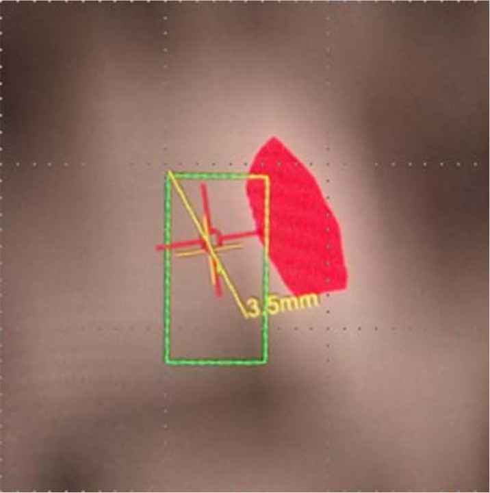
Fig. 1: A snapshot taken from FUS control GUI (InSightec) showing the heating (red spot) is more than 1 mm away from the target (green rectangle) in horizontal frequency encoding direction.