1130
Shape-Optimization of Electric Dipoles for Human Head Imaging at 7 Tesla1Centre for Functional and Metabolic Mapping, Robarts Research Institute, London, ON, Canada, 2Medical Biophysics, University of Western Ontario, London, ON, Canada
Synopsis
Dipole antennae have been proposed as an alternative solution for RF transmission at ultra-high field (UHF) strengths. However, adapting dipoles to achieve self-resonance, while minimizing SAR for a given transmission field homogeneity, is challenging given the geometry of the human head. In this study, the design of dipole elements is performed via computer aided shape optimization and is demonstrated to meet several of these design parameters. The final design relies upon meandered-conductor paths to produce electromagnetic fields that minimize local SAR without the use of additional RF shimming or pulse design algorithms.
Introduction
Ideal current patterns related to the transverse magnetization occurring at Ultra-High-Field (UHF) transition away from an entirely reactive near-field RF excitation1. Following the Ultimate Intrinsic SNR (UISNR) method, it has been demonstrated that loop-based elements can obtain UISNR for spherical samples1. But, for cylindrical targets, the longitudinal component of UISNR currents may require the use of elements that induce linear current patterns – i.e. electric dipoles.
With the dimensions of the human head not clearly defined by either a purely spherical or cylindrical geometry, the concept of adapting electric dipoles to better approximate UISNR current patterns for both SAR reduction and excitation efficiency is investigated in this study via shape-optimization.
Methods
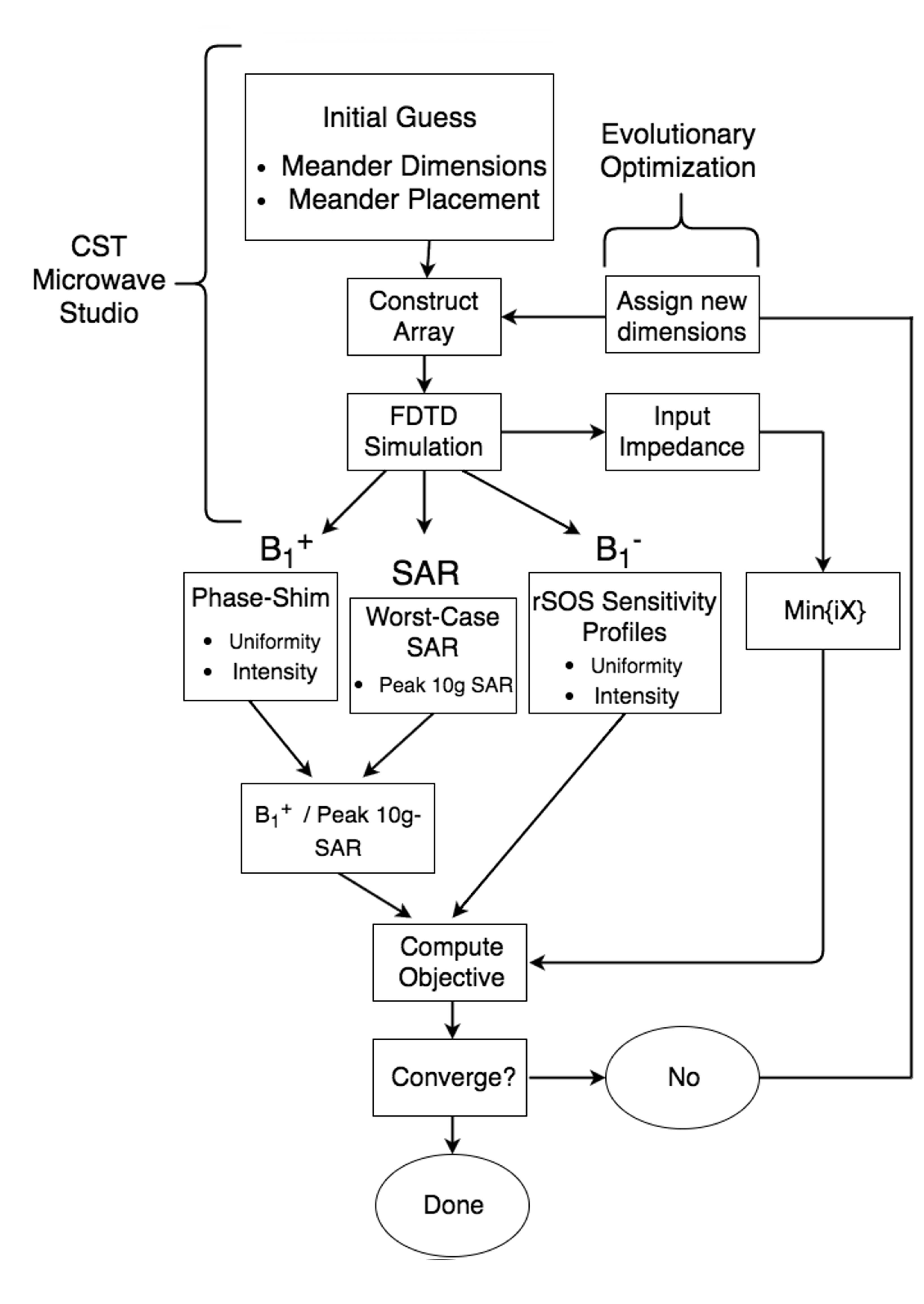
Shape optimization of the dipole array was performed with a covariance matrix-adapted evolutionary (CMA-ES) algorithm. This routine is well suited for a shape-optimization procedure that contains an extremely large parameter space and correlated objective functions.
The dipole array is designed to operate in transceive mode with eight independently controlled channels. For design, it was modeled with full-wave finite difference time domain (FDTD) software utilizing a numerical head phantom. Following a post-processing RF shim, CMA-ES iterative called the FDTD engine to minimize the following objectives:
1. Imag{Zin(297.2 MHz)} = 0.
2. Max( || B1+/10-g SAR || ).
3. Min(Variance( || B1+ || )).
4. Max( Mean || B1- || )
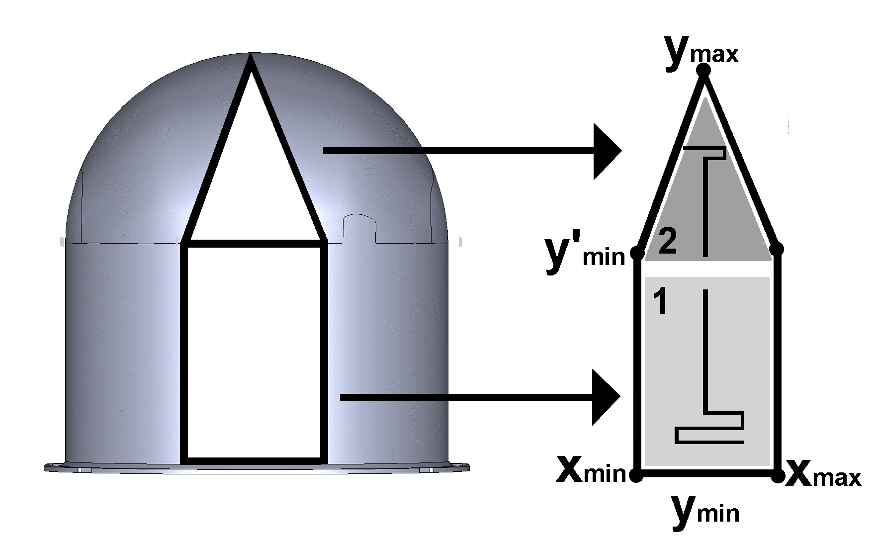
These objectives ensured: (a) self-resonance of the dipole and (b) reduced 10-g SAR for a target transmit field homogeneity. Fig. 1 demonstrates the optimization routine. As seen in Fig. 2, a helmet was chosen as the former upon which the dipole elements were conformed. Individual elements in the array were confined to a portion of the total surface area such that overlap between elements was eliminated and that ease of construction was accounted for.
The definition of the dipole elements was performed via the following:
1. Individual points were assigned inside the bounds (see Fig. 2).
2. The conductor path was then defined via a linear interpolation between the selected 3D-points.
3. The conductor path was then extruded as a planar conductor.
The interpolated line was then projected onto the helmet former, as visible in Fig. 2.
Results
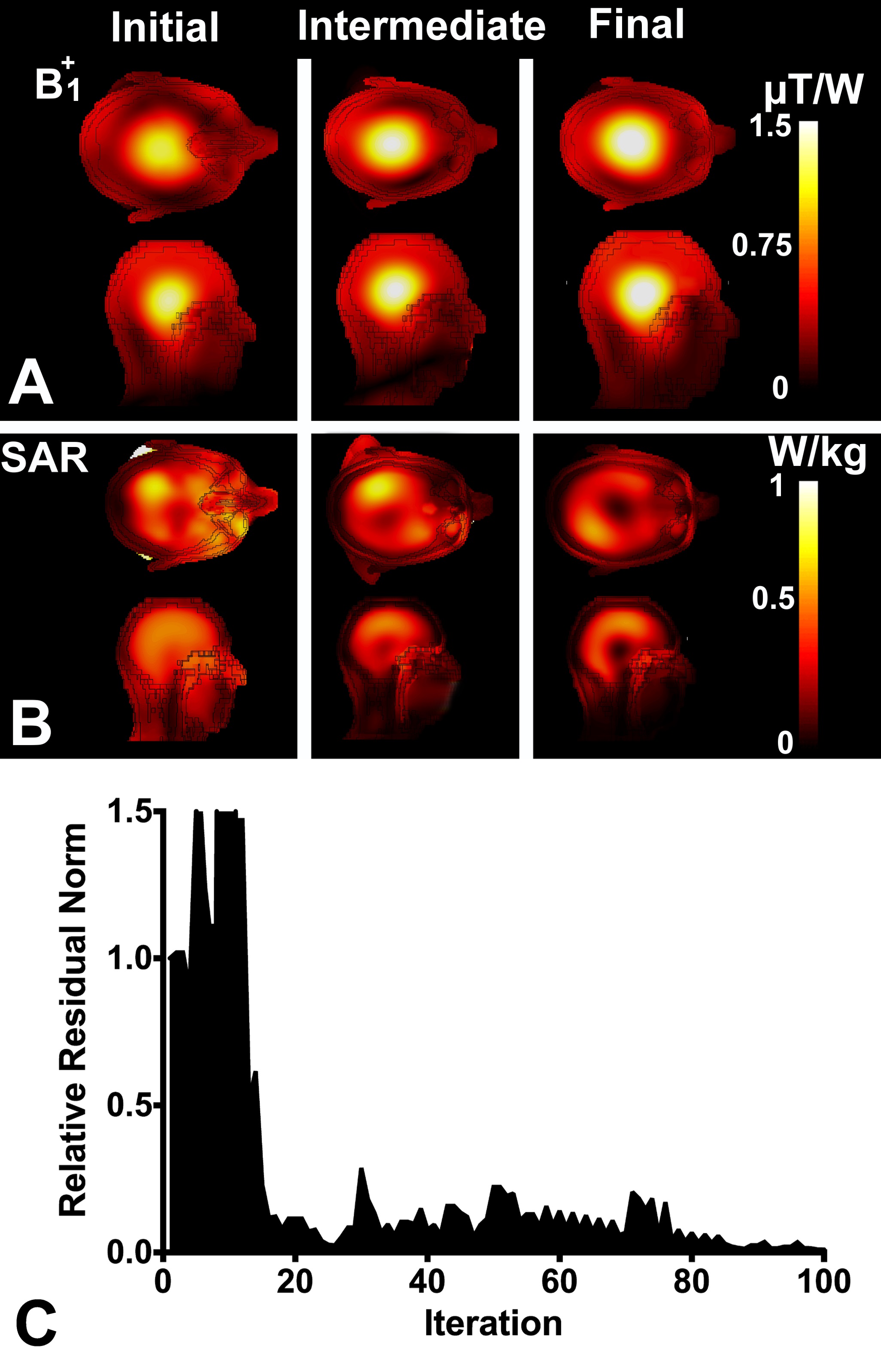
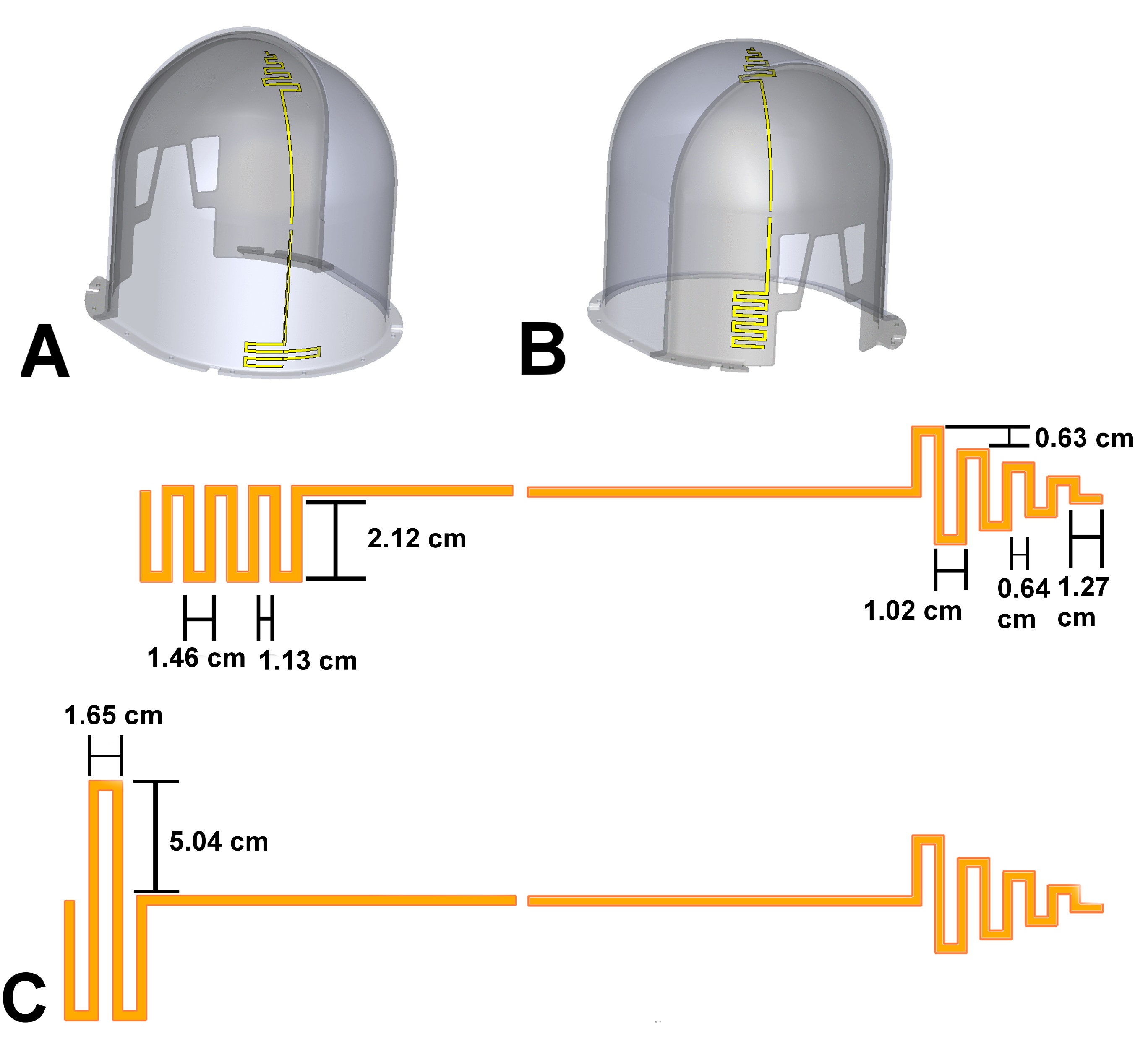
A time-lapse of the optimization routine is presented in Fig. 3 with the final dipole dimensions provided in Fig. 4.
The dipole array was constructed on an elliptical former (minor and major axes: 17 cm and 20.5 m, respectively) and was composed of eight resonant dipoles implemented with 32 mm wide 2 oz. copper traces, routed atop 0.79-mm-thick garolite. Dipoles were matched to 50 Ω via low-pass PI matching circuits utilizing two variable capacitors (1 – 30 pF, Johanson Manufacturing, NJ) and one variable inductor (25 – 34 nH, Coilcraft, IL, USA). Sleeve baluns were constructed using triaxial cable (double braid shield, 20 AWG, Belden, IN, USA), and were directly fed to the dipole matching circuit from externally mounted BNC connectors.
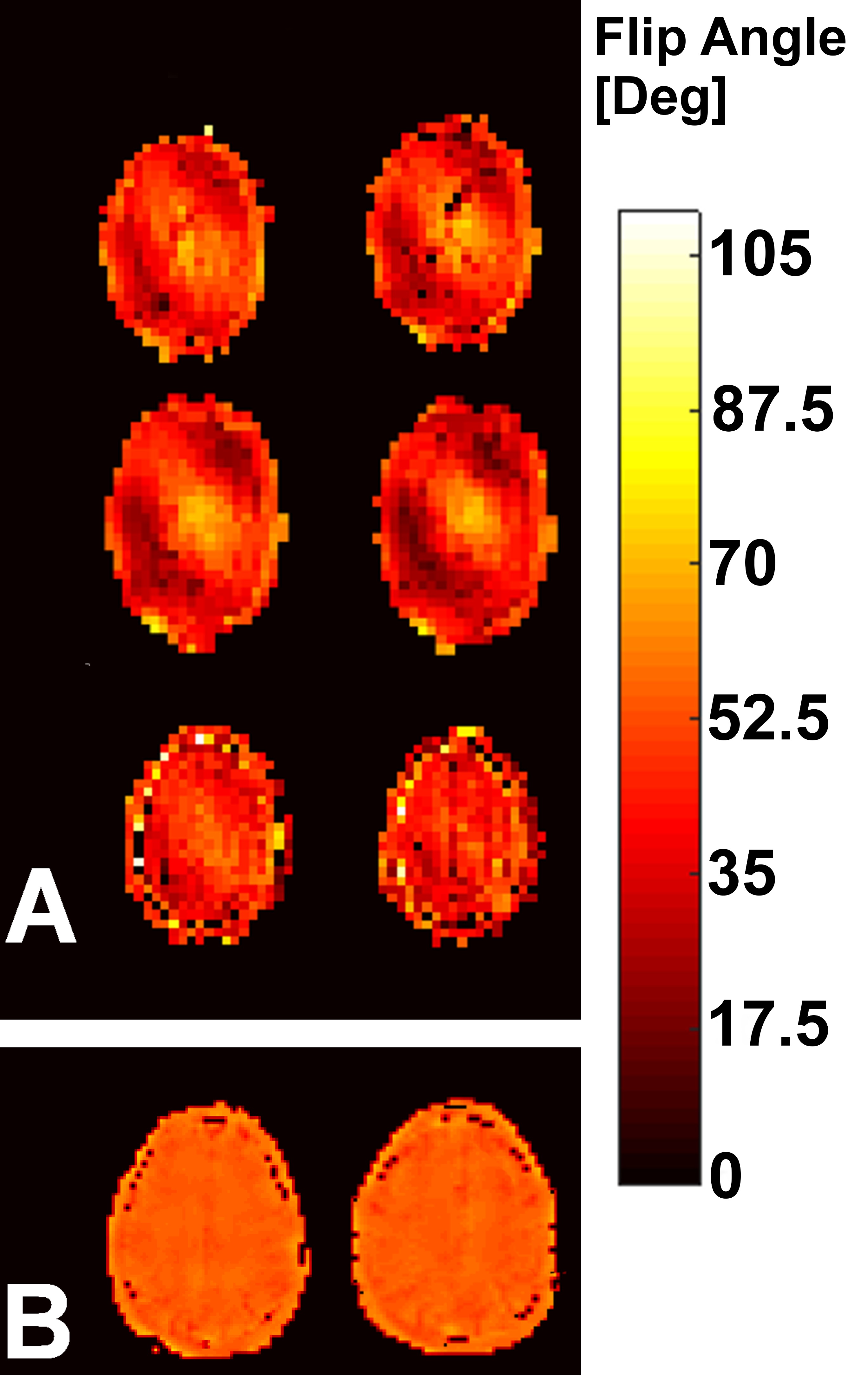
The conformal dipole coil required a 101 V reference voltage to achieve a 70º flip-angle across the entire brain with a 1-ms square pulse and a 96 V reference voltage to achieve a 70o flip-angle across a 5-mm thick, central axial slice in the brain with a 1-ms square pulse. These reference voltages were related to B1+ efficiencies of 1.6 μT/√kW for the entire brain and 1.7 μT/√kW across the axial slice.
The transmit field uniformity achieved across the entire head is demonstrated with flip-angle maps in Fig. 5a for a magnitude least-squares (MLS) shim solution and Fig. 5b for a slice-optimized spokes RF pulse design. The standard deviation of the transmit field, after performing MLS shimming, over the axial, sagittal, and coronal planes of the whole-brain shim solution was 18%, 12%, and 14%, respectively. The standard deviation of the transmit field over the whole brain volume (to the posterior-most extent of the cerebellum) was 20%. The standard deviation of the transmit field, after performing RF-spokes slice optimization, over the central axial slice was 7.5%.
The total and peak 10-g SAR, normalized to 1 W accepted input power per channel, was 0.163 W/kg and 0.601 W/kg for the dipole array, respectively.
Conclusion
Shape optimization exploits the unique degree-of-freedoms encountered with open-ended dipoles. The effect of electrically shortening a dipole antenna for use in human head imaging provides a unique opportunity to generate more SAR-efficient EM fields due to the optimization of conductor placement in the array.Acknowledgements
No acknowledgement found.References
1. Lattanzi, R. et. al., Ideal current patterns yielding optimal signal-to-noise ratio and specific absorption rate in magnetic resonance imaging: computational methods and physical insights. MRM, 2012.Figures