1128
High dielectric constant (HDC) disk dipoles for 10.5T imaging1Center for Magnetic Resonance Research, University of Minnesota, Minneapolis, MN, United States, 2Center of NMR Research, Department of Radiology and Neurosurgery, Penn State College of Medicine, University Park, PA, United States, 3Materials Science and Engineering, Pennsylvania State University, University Park, PA, United States
Synopsis
A small coil element is developed for 10.5T imaging by affixing an end-loaded 82mm long dipole to a high dielectric constant (HDC) flat disk. This coil element produces localized but very high B1 fields similar to a loop of a similar diameter without suffering from diverging B1+ and B1- that loops experience at high field. Furthermore, these elements are inherently highly decoupled in all possible spatial configurations, making them well suited to use in large, densely packed transmit arrays.
Objective
Develop and test an array of very short dipole elements which employ a high dielectric constant (HDC) flat disk of 82 mm diameter and 16 mm thickness. Compare the performance of these dipole elements to loops of a similar diameter (82 mm) as well as fractionated and half-wave dipole elements (20 cm length) at 10.5T (447 MHz).Methods
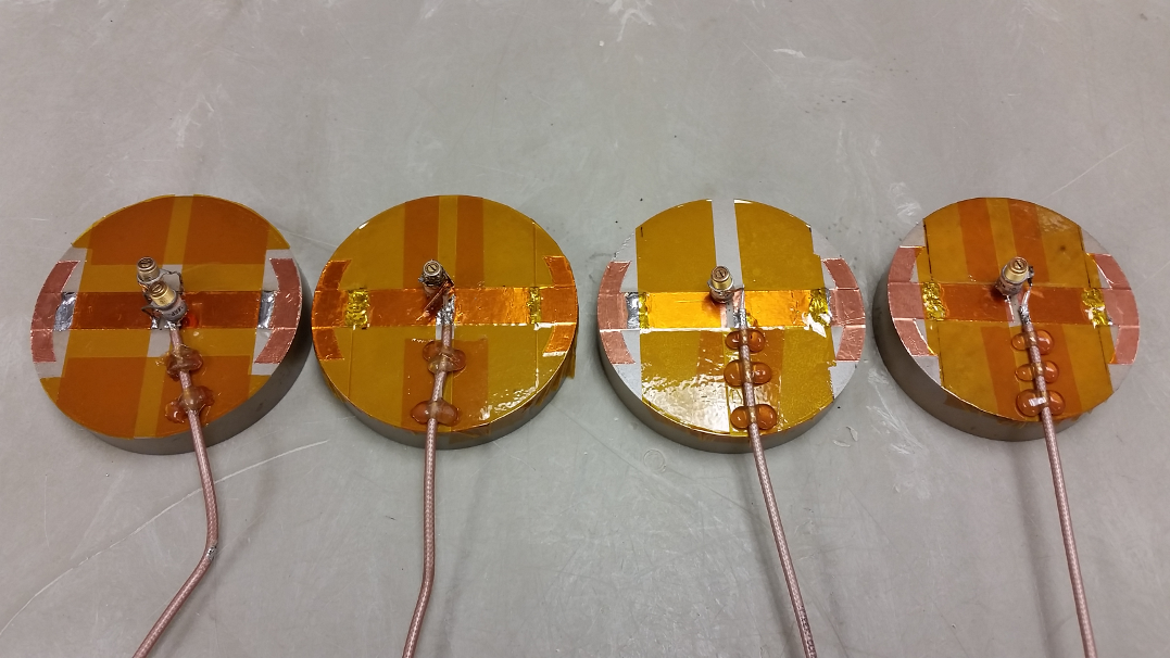
The HDC disk employed in this work was made of TiO2 using a conventional sintering technique. The electromagnetic (EM) properties were determined using a resonance technique (εr=100.26, σ=1.1 mS/m). The lowest resonant frequency was measured at 0.9845 GHz1. All coil elements constructed were tuned and tested on a cylindrical phantom 32cm(L) x 16cm(D). The phantom solution (47.6% H2O, 1.3% NaCl, and 51.1% Sucrose2) EM properties were measured at 447 MHz with a DAKS-12 (SPEAG, Zürich, Switzerland) to be: εr =55, σ=0.60 S/m. To ensure a stable resonant frequency for the dipole element as well as achieve the shortest possible dipole length, copper tape (12.7 mm wide) was affixed directly to the flat top of the HDC disk. The maximum end-to-end length of the dipole is 82 mm. Conformal end-loading segments 6.35 mm wide, located at the ends of the dipole, reduced the resonant frequency to 447 MHz3. The dipole was impedance matched using a series variable capacitor (NMAF4HV, Voltronics, NY, USA). The four elements built are pictured in Figure 1. The elements were not mounted inside a coil housing and could thus be arranged in a variety of ways on the imaging sample. Elements were highly decoupled (S21 ≤ -27 dB) in all possible spatial configurations.
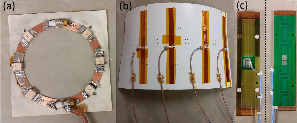
This HDC disk dipole was compared to a loop with the same diameter and dipoles at their self-resonant length. An 82 mm diameter loop was constructed using 8 segments with 13 mm trace width (Figure 2a). A half-wave dipole element was constructed with 12.7 mm copper tape affixed to a 5mm thick PTFE sheet. While closely coupled to the phantom, the dipole was adjusted to its self-resonant length of 20 cm. Four of these dipole elements spaced 84 mm apart were built as a transceiver array (Figure 2b). Each dipole was inherently matched (no lumped components necessary) to better than -20 dB (S11). All elements were highly decoupled (S21< -30 dB). The array was also tested with padding which placed the conductors 16 mm from the phantom (identical to the HDC disk dipole). The padded dipoles were lengthened to the new self-resonant length of 22.7 cm.
For a well-known reference, the fractionated dipole4, which was previously shortened and modified for body imaging at 10.5T5, was also compared (Figure 2c). This element was tested in two configurations. First the element was padded with 12 mm of foam to achieve S11= -14.4 dB (matching circuitry is fixed). Then the element was closely coupled to the phantom (separated by only the 3/8” Polyetherimide coil housing), despite a poor S11= -8.4 dB.
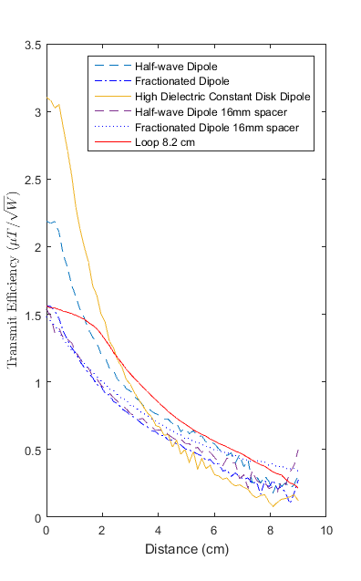
Results
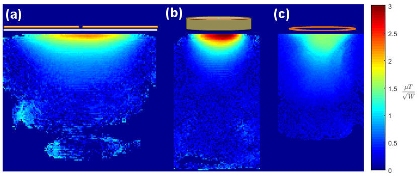
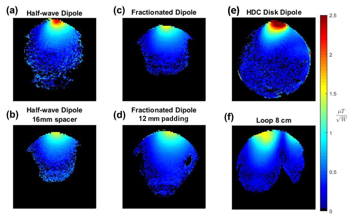
Sagittal and axial B1 maps are shown in Figure 3 and 4, respectively. The HDC disk dipole produces a highly localized B1 field with a radius approximately equal to that of the HDC disk (Figure 3b). Peak B1+ exceeds that of the loop and does not suffer from diverging B1+ and B1- fields (Figure 4f) that occurs at high B0 field. All comparison coil elements, while having lower peak B1+, radiate more deeply into the phantom (Figure 5) than the HDC disk dipole. Thus, these elements perform better at depth when working as an array. In contrast to a 4-element array of HDC disk dipoles (Figure 6b), the 4-channel half-wave dipole array tested efficiently radiates deep into the phantom (Figure 6a).Discussion & Conclusion
The HDC disks allow for construction of very short dipoles with
a highly localized sensitivity profile. This may be advantageous for examining
structures near the surface of an imaging sample, but a drawback if imaging large samples. However the HDC disks and dipole
used were not optimized. These HDC disk dipoles behave similarly to loops,
but have higher peak transmit efficiency and decoupling, and do not suffer from diverging B1+ and B1-.
Because they are small and inherently decoupled, they could be used in densely packed high channel count transmit arrays. Furthermore, SAR distribution can
be modified by rotating the dipole elements to exploiting dark modes.6
Future work will examine the SAR characteristics of these elements and the optimal spatial configuration for maximizing transmit efficiency and SNR while minimizing SAR.
Acknowledgements
Funding for this research came from NIH-NIBIB grants P41 EB015894, S10 RR029672, and R24 MH106049.References
1. Rupprecht S, Wiesner H, van De-Mortelle PF, Lee BY, Luo W, Zhu XH, Duck I, Adriany G, Ugurbil K, Lanagan MT, Chen W, Yang QX. Prospect of SNR and SAR Improvement on Whole-body Human 10.5T Scanner using High Dielectric Material. Proc Intl Soc Mag Reson Med 2016; 24: p. 396.
2. Beck BL, Jenkins KA, Rocca JR, Fitzsimmons JR. Tissue-equivalent phantoms for high frequencies. Concepts Magn. Reson. [Internet] 2004;20B:30–33. doi: 10.1002/cmr.b.20002.
3. Lagore RL, DelaBarre L, Tian J, Adriany G, Eryaman Y, Vaughan JT. End-Loaded Dipole Array for 10.5T Head Imaging. In: Proc. Intl. Soc. Mag. Reson. Med. 24 ; 2016. p. 2138.
4. Raaijmakers AJE, Italiaander M, Voogt IJ, Luijten PR, Hoogduin JM, Klomp DWJ, van den Berg CAT. The fractionated dipole antenna: A new antenna for body imaging at 7 Tesla. Magn. Reson. Med. [Internet] 2015. doi: 10.1002/mrm.25596.
5. Ertürk MA, Wu X., Eryaman Y, Van de Moortele P-F, Auerbach EJ, Lagore RL, DelaBarre L, Vaughan JT, Ugurbil K, Adriany G, Metzger GJ. Toward imaging the body at 10.5 tesla. Magn. Reson. Med. 2016. doi:10.1002/mrm.26487
6. Eryaman Y, Guerin B, Keil B, et al. SAR Reduction in 7T C-Spine Imaging Using a “Dark Modes” Transmit Array Strategy. Mag. Reson. Med. 2015;73(4):1533-1539. doi:10.1002/mrm.25246.
Figures