1122
Homogeneous high-flip-angle 3D localization by parallel transmission at 9.4T1Max Planck Institute for Biological Cybernetics, Tuebingen, Germany, 2Department of Chemistry, Technical University of Munich, Garching, Germany, 3Institute of Physics, Ernst-Moritz-Arndt University Greifswald, Greifswald, Germany
Synopsis
This work presents in vivo experimental result of high-flip-angle multi-dimensional parallel transmission at a 9.4T human whole-body MRI scanner. A 2D pTx saturation pulse (90°) and a slice selective 3D pTx excitation pulse (60°) were designed by using an algorithm that combines LSQR and optimal control (OC) methods and enables high-flip-angle pTx pulse design with a strict constraint of transmit power. An actual flip angle imaging (AFI) sequence was coded to measure the flip angle map of the pre-saturated slice excitation profile achieved by the sequentially implemented pTx pulses.
Introduction
Parallel transmission technology (pTx) [1] helps to improve excitation uniformity, facilitates inner volume selection or field-of-view reduction and allows for pulse acceleration. By far the most related studies demonstrate low-flip angle excitation at ultra-high field [2], while the design of high flip angle parallel excitation pulses remains challenging due to 1) the limited spatial coverage of the RF field in case of the most common configuration of 8-transmit channels), 2) the very large inhomogeneity of the transmit field, 3) the limited power delivered by the RF amplifiers of UHF parallel TX systems (usually 8 x 1kW and 50% line loss) and 4) specific absorption rate (SAR) limitations. An algorithm that combines both least squares optimization (LSQR) [3] and the optimal control (OC) method [4] was recently proposed by Shao et al [5] to calculate spatial-spectral pulses under these strict constraints. In this work, this algorithm is introduced to achieve high-flip-angle uniform 3D localization profile combining 2D pre-saturation and homogeneous slice-selective excitation, and is verified with experimental results from a 9.4 Tesla whole-body human scanner equipped with an 8-channel PTX system.Methodology
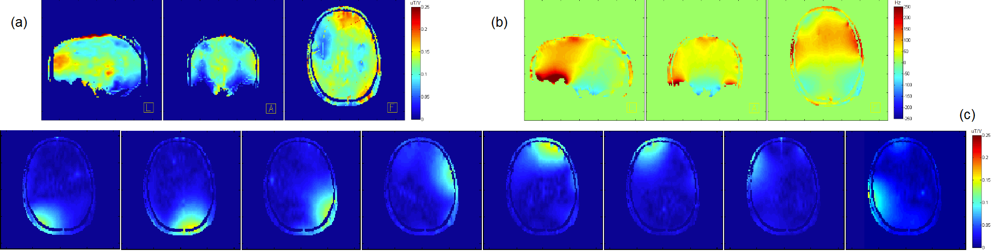
B1 map and basic imaging settings The B1+ field maps were acquired with a home-built 8-channel Tx, 16-channel Rx array head coil [6] in a healthy volunteer on a 9.4T whole body human MRI scanner (SIEMENS Healthcare, Erlangen, Germany), using the 3D actual flip angle imaging (AFI) method [7]. The B1+ field map and the B0 field map are shown in Fig 1. The desired 3D localization profile for this proof of principle study is a uniformly excited slice (thickness = 4mm, flip angle = 60°) with a uniformly pre-saturated profile (2D, 90°) of the word “MPI”. An AFI sequence (TR1 80ms / TR2 400ms / resolution 1.72mm*1.72mm*3mm) was coded and modified to implement a pTx saturation pulse and a pTx excitation pulse, in order to measure the flip angle profile generated by the two sequentially applied pulses.
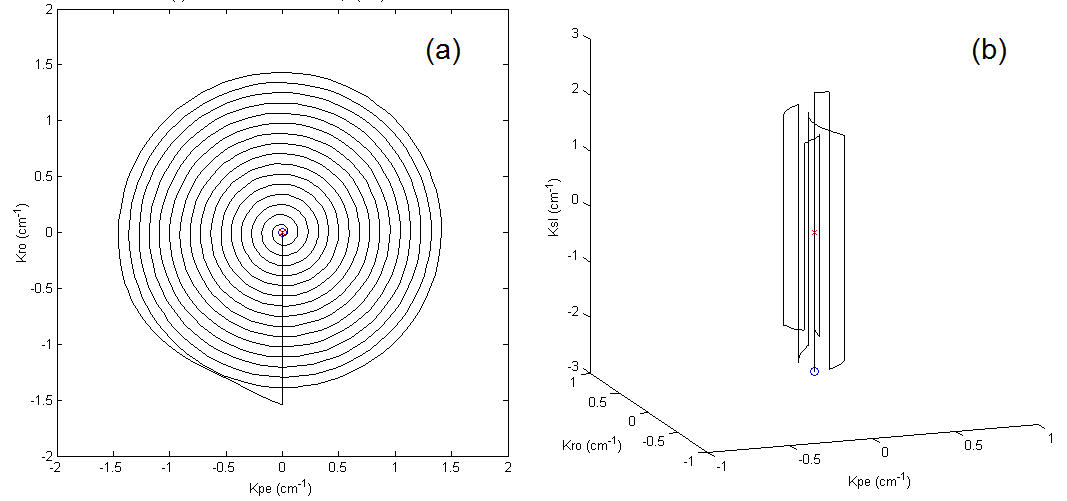
2D saturation pTx-pulse design A 2D spiral trajectory (FOV = 22cm, dr = 3.4mm, Acc = 2) was used as shown in Fig 2(a). A spiral-type trajectory is chosen because of its traversing efficiency and the accordance of its gradient amplitude and the RF weighting map distribution that lowers the RF amplitude in need. The RF pulses were designed based on an iterative small-tip-angle (STA) approach [8], during the iterative design process of which, the RF pulses were first calculated using the LSQR method, and were afterwards passed as an initial guess to the subsequent calculation using the OC method [5]. This procedure ensured convergence to a global optimum under strict constraints of the maximum applicable RF amplitude.
Slice selective excitation pTx-pulse design The slice selective excitation pulse was designed using the fully 3D pTx pulse design method that was proposed by Shao et al [9, 10]. This method calculates a “trajectory container” which represents the excitation k-space area where the RF energy deposition is highly demanded in achieving the target profile, then chooses a typical 3D k-space trajectory and shapes it according to the scale of the “trajectory container” in order to reduce the pulse duration without losing fidelity, and finally, calculates the RF pulses upon the determined k-space trajectory based on the iterative STA approach and the LSQR-OC combine algorithm. In this case a spoke-type trajectory is adopted and shaped as shown in Fig 2(b), because of its high efficiency in traversing the large kz scale that is required for a thin slice selection. The parameters are FOV = 22cm, dr = 6.8mm*6.8mm*2mm, Acc = 2.
Results and discussion
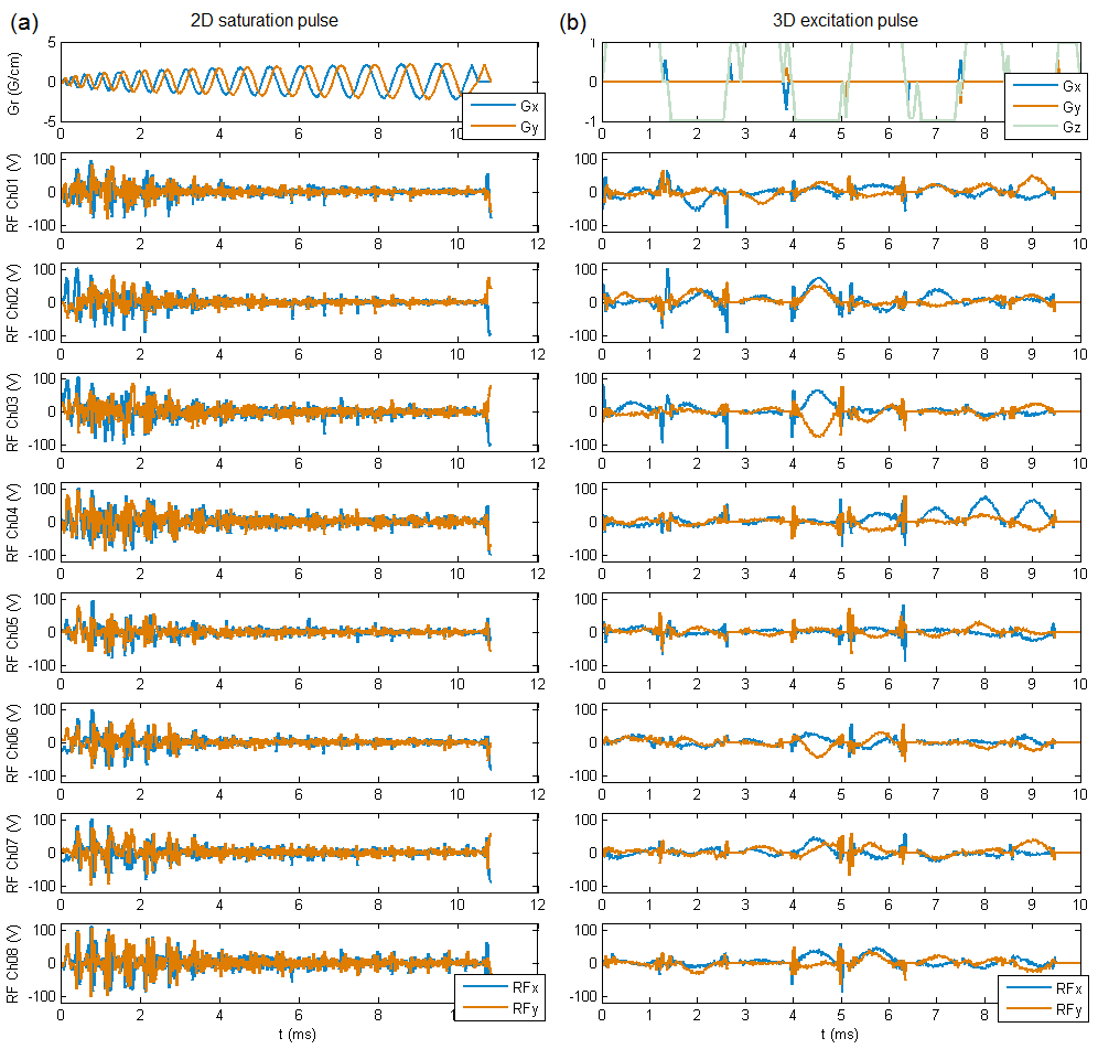
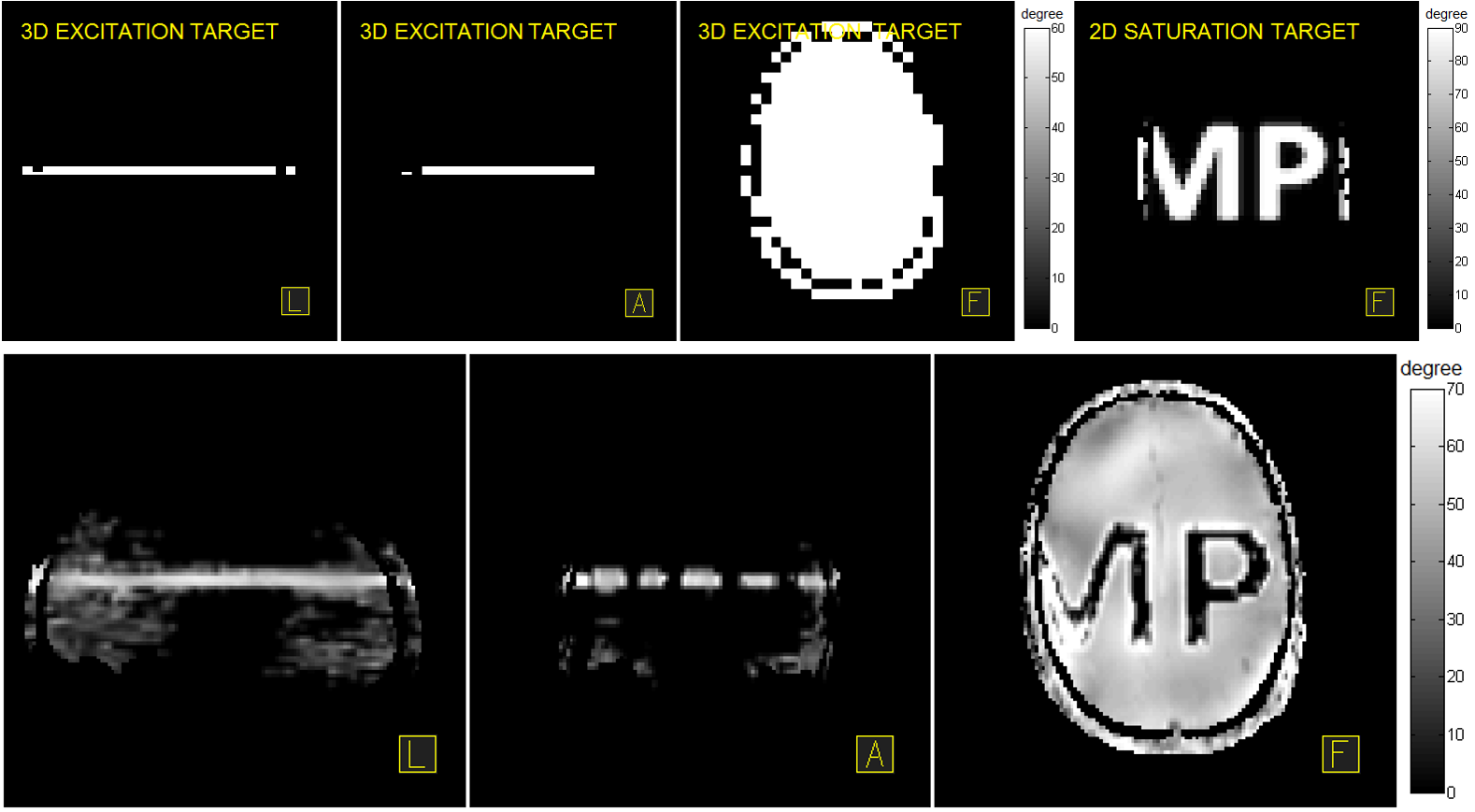
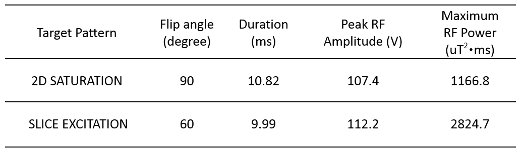
Fig 3 shows the designed gradient and RF pulses of 2D saturation and 3D excitation cases. Fig 4 shows the flip angle maps of the target (upper row) and the achieved (lower row) 3D localization profile. Table I shows the flip angles, pulse durations, peak RF amplitudes and maximum possible RF power efficiency. It can be seen from Fig 4 that the saturation profile matches well the target except a defective part of “M” close to the skull which could be caused by local imprecisions of the AFI sequence due to its dynamic range limitations. It can also be seen from Fig 4 that a uniform 60° thin-slice excitation was achieved but a few sidebands were also generated near the sinuses and vestibule tubes where severe B0 inhomogeneities arise. The experimental result indicates that homogeneous high-flip-angle 3-dimensional localization by parallel transmission is feasible at a 9.4T whole-body MRI scanner, but further investigation is required to improve the through-slice profile accuracy against B0 inhomogeneity.Acknowledgements
ERC Starting Grant Project SYNAPLAST MR.References
[1] Katscher et al., MRM 49: 144-150 (2003). [2] Padormo et al., NMR in Biomedicine 29(9): 1145-1161 (2016). [3] Jacobsen et al., BIT Numerical Mathematics 43: 975–989 (2003). [4] de Fouquieres et al., JMR 212, 412-417 (2011). [5] Shao et al., ISMRM: 918 (2015). [6] Avdievich NI et al., ISMRM: 169 (2015). [7] Yarnykh VL, MRM 57(1): 192-200 (2007). [8] Grissom et al., MRM 53: 620-629 (2006). [9] Shao et al., IEEE-TMI 31,5: 997-1007 (2012). [10] Shao et al., ISMRM: 4278 (2016).Figures