1055
COSI Transmit: Open Source Soft- and Hardware Transmission System for traditional and rotating MR1Berlin Ultrahigh Field Facility (B.U.F.F.), Max Delbrück Center for Molecular Medicine in the Helmholtz Association, Berlin, Germany, 2Physikalische Technische Bundesanstalt (PTB), Berlin, Germany, 3Experimental and Clinical Research Center (ECRC), a joint cooperation between the Charité Medical Faculty and the Max Delbrück Center for Molecular Medicine, Berlin, Germany, 4MRI.TOOLS GmbH, Berlin, Germany
Synopsis
As part of the open source imaging initiative (www.opensourceimaging.org), a collaborative effort to build an open source MRI, we proposed and built a transmission/reception RF system mostly consisting of open source components for traditional and rotating spatial encoding schemes. COSI Transmit is based on a GNU Radio compatible software defined radio (SDR) as a spectrometer, a 1kW RF-power amplifier, T/R switch, low noise preamplifier and a transmit/receive solenoid RF coil. The system operates in the frequency range from 1.8-30MHz (B0=0.042-0.7T) and can potentially be extended to B0=1.27T. Material cost of the system is ~3000€.
Purpose
MRI is a crucial medical device that is beyond the reach of many patients throughout the world1. Cost effective open source imaging (COSI) is part of the open source imaging initiative (OSI²) currently building an affordable open source MRI system in order to address this issue2. Here we present COSI transmit, an open source transmission/reception system for low field (B0=0.042-0.7T) MRI of traditional and rotating spatial encoding schemes3. COSI transmit consists of a spectrometer, RF power amplifier (RFPA), transmit/receive switch, low noise preamplifier and RF coil.Methods
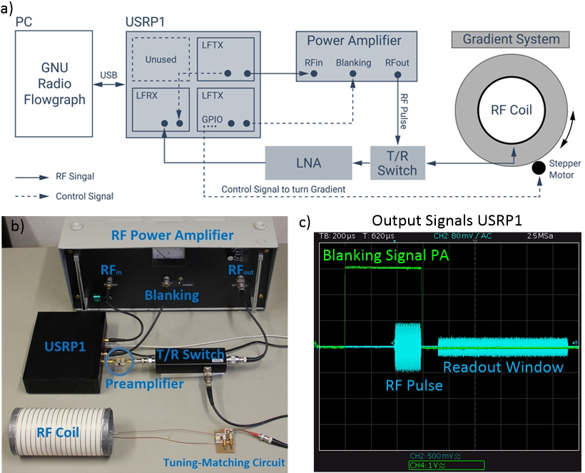
A schematic of COSI transmit modules is displayed in Fig.1a.
The primary requirement for the spectrometer hardware was GNU Radio4 and gr-MRI5 compatibility. This approach allows hardware independent developments of imaging techniques. An USRP16 SDR (f=DC-6GHz, ADC: 12bit 64MS/s, DAC: 14bit 128MS/s) was implemented with two transmit7 and one receive8 daughterboard (f=0-30MHz). We extended the gr-MRI5 code utilizing GPIO pins embedded in the board allowing the use of a single SDR for stepper motor control of rotating gradient fields used for spatial encoding9,10.
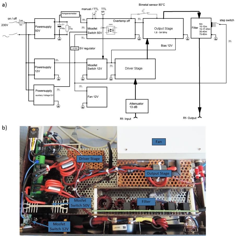
A RF amplifier (Pout=1kW peak, f=1.8-54MHz) was developed consisting of a driver stage, an output stage, a low pass filter, a blanking/unblanking circuit and a cooling circuit (Fig.2a). For the driver a two stage linear amplifier11 (gain:33-34dB, Pout=5W, f=1.8-150MHz) and for the output stage the design of W6PQL12, a 1kW peak solid state pallet amplifier (gain:22-27dB, f=1.8-54MHz) based on a power LDMOS transistor (BLF188XR) was chosen. A 1.5kW low pass filter12 at the output suppresses unwanted harmonics. A level converter is used at the SDR output to match the TTL high for RFPA unblanking. For un-/blanking the amplifier, the power supply voltage is switched on/off respectively via CMOS transistors. In addition after 3µs the LDMOS source is clamped to discharge the capacities and suppress any additional RF noise of the output stage during MR signal reception.
A passive T/R-switch13 (3-5MHz, 47dB isolation, Pmax=1.3kW) was used to connect the RF coil and the RFPA. For MR signal pre-amplification a low noise preamplifier14 is utilized (f=150kHz-30MHz, gain:18-20dB, noise figure=1-2dB).
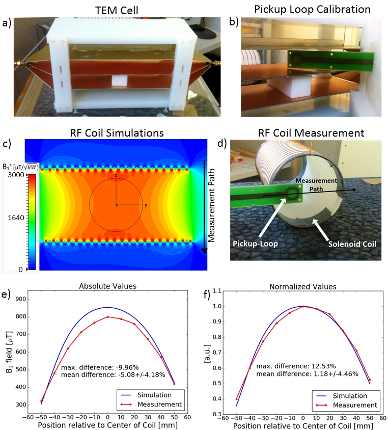
The RF coil was constructed based on electromagnetic field simulations15 for a frequency of f=3.63MHz, which is the center frequency of our prototype Halbach magnet. A solenoid design was chosen as a transmit/receive RF coil to adapt to the Halbach magnet B0 field distribution. RF coil loading was modeled by a spherical sample with 70mm diameter representing muscular tissue. The length and number of turns was adjusted to reach a homogenous B1+ field distribution inside the sample (Fig.5c).
The simulations were validated with S12-measurements16 of a pickup loop positioned along a straight line at one end of the RF coil. B1 calibration of the pickup loop was done in a known B-field of a TEM-cell17 (Fig.5a,b,d). This approach allows for a low cost validation of the EM fields at such low frequencies without using more expensive E- or H-field sensors.
Results
The spectrometer is capable of producing arbitrary shaped RF-pulses, un-/blanking the RFPA, recording acquired data and controlling rotating gradient fields (Fig.1c). Pulse length, amplitude, readout-length and –delay can be chosen freely.
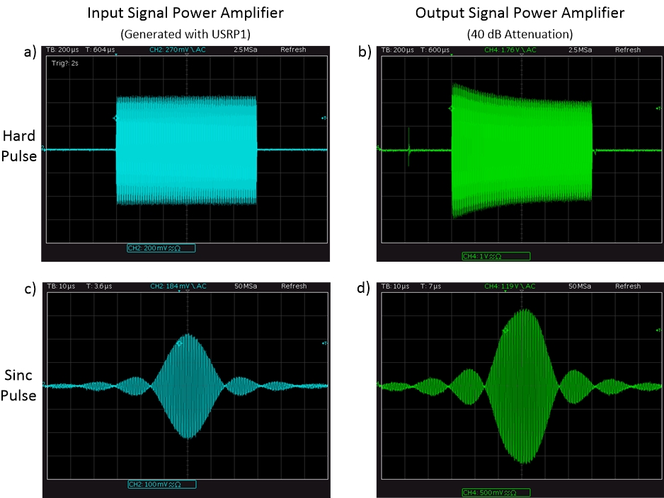
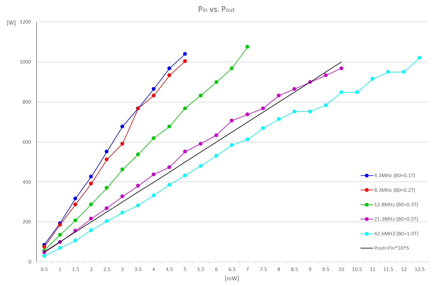
The RFPA successfully amplified rect- and sinc-pulses generated by the spectrometer (Fig.3b,d). A signal amplitude of 500mV at the input leads to an output voltage level of 200V which corresponds to a total gain factor of 52dB and a power level of 800W in a 50Ω system (Fig.3). The expected distortions observed (Fig. 3) will be addressed by digital predistortion techniques. The RFPA shows good linearity for the investigated frequency range f=1.8-54MHz (B0=0.042-1.27T) with a maximum power output of around 1kW peak power (Fig.4).
The RF coil consists of N=20 windings, length=200mm and radius=48mm (Fig.5d). The measured Q-factors are Qloaded=155 and Qunloaded=189. Simulated B1+ amplitude in the RF coil center is ~2694µT/√kW with a B1+-field inhomogeneity within the sample <3.4% (Fig. 5c). The mean difference between validation measurements and simulations was -5.1±4.2% for absolute and 1.2±4.5% for relative values. The whole system occupies a volume of around (50x30x35)cm³. The total cost of the system is ~3000€ (SDR:1000€; RFPA:1500€; T/R-Switch:370€; LNA:20€; RF-coil:100€).
Conclusion
An affordable (~3000€) MR transmission/reception system was developed by using mainly open source hardware components. In its current configuration COSI transmit can be used for B0=0.042-0.7T (extendable to 1.27T) MRI systems with traditional and rotational spatial encoding schemes. Technical documentation of the system will be made available at www.opensourceimaging.org according to the principles of open source hardware. Further work will focus on developing a fully open source spectrometer, T/R switch and RFPA module allowing to improve the performance and lowering costs.Acknowledgements
The authors would like to express their gratitude to Christopher J. Hasselwander and William A. Grissom for helpful assistance in gr-MRI.References
1 World Health Organization, “Global Health Obervatory (GHO) data: Medical equipment (density per million population)”, 2014
2 Winter L, et. al., ISMRM, 2016, #3638
3 Cooley CZ, et al., MRM, 2015;73(2):872-83
4 GNU Radio, http://gnuradio.org/
5 Hasselwander C.J., et al., JMR, 2016;270:47:55
6 USRP1, Ettus Research, Mountain View, USA
7 LFTX daughterboard (0-30MHz), Ettus Research, Mountain View, USA
8 LFRX daughterboard (0-30MHz), Ettus Research, Mountain View, USA
9 Winter L, et al. ISMRM, 2015, #3568
10 Blümler P, Conc Magn Reson Part B: Magn Reson Eng, vol. 46, pp. 41-48, 2016.
11 Funkamateur, Bausatz für QRP-Linear-Endstufe, DL2EWN, http://www.box73.de/
12 W6PQL, http://www.w6pql.com/1kwsspafor18-54mhz.htm
13 NMR Service GmbH, Erfurt, Germany
14 LNA4HF, 9A4QV, http://lna4hf.blogspot.de/
15 CST MWS 2012, Darmstadt, Germany
16 Spectrum analyzer, Rohde & Schwarz, München, Germany
17 Klepsch T., et al., BMT, 2012; 57(1)
Figures